CUTMASTER 40MM
SERVICE 5-20 Manual 0-5085
E. With CURRENT CONTROL
POTENTIOMETER set at maximum, output
current is only 60 amps.
1. Tip is touching the work piece, Drag mode.
a) Lift tip off work piece
2. Defective Pilot IGBT on Main PCB 1
a) Check per section 4.10-I
3. Open Sync cable between J14 on Main PCB 1 and
40Amp PCB 5.
a) Check continuity and replace if open.
4. Open connection between J13 on Main PCB 1 to
J4 on 40A PCB 5.
a) Check continuity.
5. Defective 40Amp PCB 5.
a) Replace 40Amp PCB 5
G. In RAPID AUTO RESTART mode, with
torch switch closed, the pilot does not
start immediately when the cutting arc
extinguishes
1. Defective Logic PCB 3
a) Replace Logic PCB 3
H. INTERNAL ERROR FAULT indicator and 90
PSI LED flashing
1. There has been a microprocessor problem.
a) Turn ON/OFF SWITCH to OFF position and
then turn to ON position to clear the error
2. Defective Logic PCB 3.
a) Replace Logic PCB 3.
5.10 CNC Interface Problems
A. Nothing happens when jumper is installed
between J2-3 to J2-4.
1. Defective Automation Interface PCB 4.
a) Measure voltage on PCB 4 between J1-6 to J1-8
for 12VDC.
If 12VDC is present replace Automation Interface
PCB 4
2. Defective Main PCB 1.
a) Measure voltage on Main PCB 1 between J1-6
to J1-8 for less than 2VDC.
If voltage is less than 2VDC, replace Main PCB `1.
B. No OK-TO-MOVE signal while cutting.
1. Defective Main PCB `1
a) Measure voltage on PCB 4 between J1-1 to J1-3
for 12VDC while cutting.
If 12VDC is present, replace PCB 1
2. Defective Automation Interface PCB 4
a) Measure voltage on PCB 4 between J1-1 to J1-3
for less than 2VDC while cutting.
If voltage is less than 2VDC, replace PCB 4.
C. ARC VOLTS signals are low or not present
1. Defective Automation Interface PCB 4
a) Replace PCB `4
5.11 Test Procedures
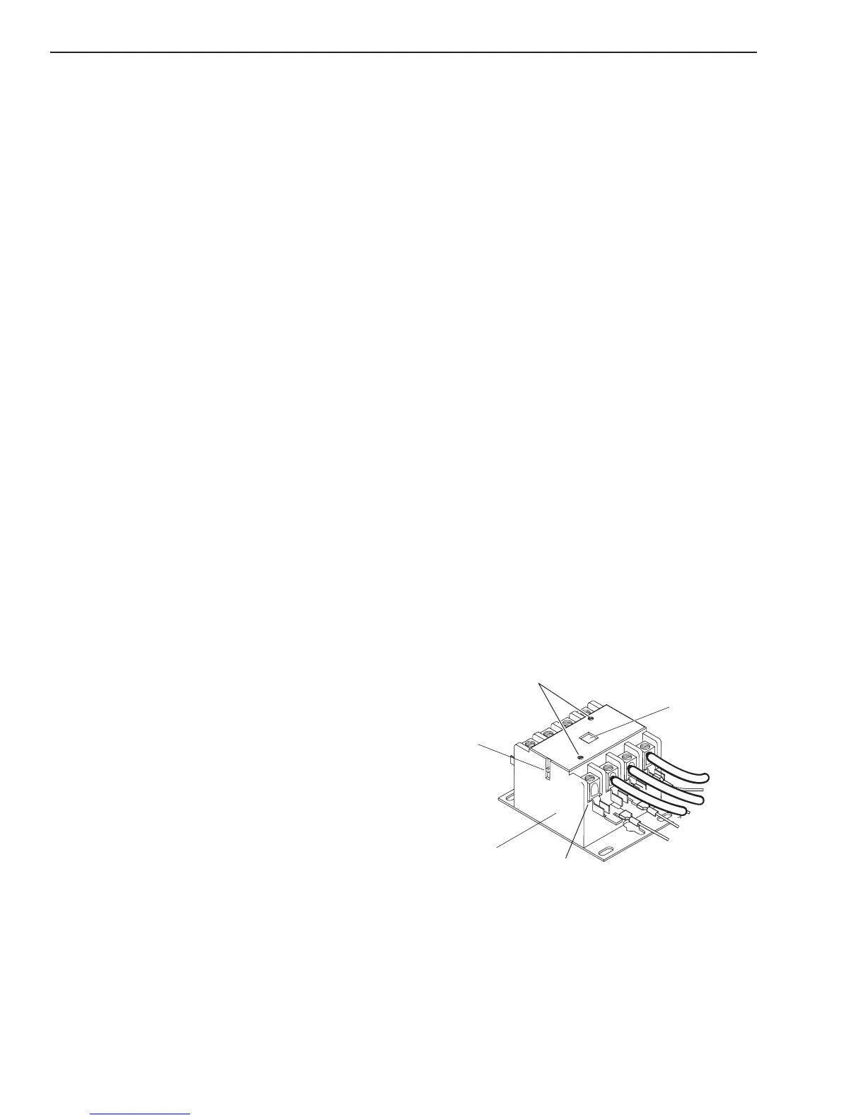
A. Main Contactor (W1) Test
1. Check continuity between:
L1 to T1
L2 to T2
L3 to T3
L4 to T4
The contacts should be open – no continuity. If con-
tinuity is found, disconnect J1 from the Main PCB 1
and recheck. If continuity still exists, replace W1. If
disconnecting J1 from Main PCB 1 removes the short,
replace the Main PCB 1.
L4 L3 L2 L1
T4 T3 T2 T1
Actuator Arm
Cover Screws
Input
Main Contactor
 Loading...


