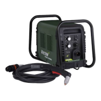
CUTMASTER 40MM
SERVICE 5-16 Manual 0-5085
If gas DOES flow out of SOL1 when the unit is in SET
mode, reconnect SOL1 to the ATC connector.
4. Defective torch solenoid.
a) Measure the coil terminals of the torch mount-
ed gas solenoid SOL2 for 24VAC. If present,
replace SOL2.
5. Defective Main PCB 1.
a) Measure on Main PCB 1 between J2-20 to
GND1 for less than 2VDC.
If voltage is 12VDC replace Main PCB 1
b) Measure on Main PCB between J2-11 to GND1
for less than 2VDC. If voltage is less than
2VDC replace Main PCB 1.
6. Defective Logic PCB 3.
a) Measure on Main PCB 1 between J2-11 to
GND1 for less than 2VDC. If voltage is 12VDC,
replace Logic PCB 3.
R. Cannot adjust gas pressure.
1. Inlet gas pressure is too low
a) Increase inlet gas pressure to 95-120 psi
2. Faulty regulator.
a) Replace Regulator.
If Air flow changes but display does not:
3. Faulty Logic PCB 3.
a) Measure on Logic PCB 3 for 12 VDC between
TP3 to TP1. If voltage is low or not present,
replace Logic PCB 3.
4. Faulty Pressure transducer.
a) Measure on Logic PCB 3 between J3-2 to TP1
while adjusting the Pressure regulator from
Min to Max. Voltage should adjust from
0-4.5VDC. If voltage does not change, replace
the Pressure Transducer.
5. Faulty Logic PCB 3.
a) Measure on Logic PCB 3 between J3-2 to TP1
while adjusting the Pressure regulator from
Min to Max. Voltage should adjust from
0-4.5VDC. If voltage does change, replace the
Logic PCB 3.
S. AC LED ON, TEMP LED is OFF, GAS LED
is ON. Fan MOT 1 turns ON, plasma gas
not flowing. (Earlier revision units).
1) Open connection between J2 connector on Capaci-
tor PCB 2 to J3 connector on 40A PCB 5.
a) Check continuity.
2) Defective Main PCB 1.
a) Measure for approximately 325VDC on the
CAPACITOR PCB 2 between MTH 1 to MTH
7. Replace if no voltage present.
3) Defective Capacitor PCB 2.
a) Disconnect plug from J2 connector on Capaci-
tor PCB 2 and measure for 12VDC between
J2-1 to J2-2. If low or missing, replace PCB 2.
4) Defective 40A PCB 5.
a) Disconnect plug from J4 on 40A PCB 5. If fan
MOT 1 turns OFF, replace PCB 5.
5) Defective Main PCB 1.
a) Replace PCB 1.
5.08 Pilot Arc Problems
A. AC LED ON, TEMP LED OFF, GAS LED
ON. Nothing happens when START signal
is active. No gas flow, DC LED OFF, fans
MOT 1-3 do not turn ON.
1. Problem in the torch and leads switch circuit (or
remote pendant or CNC signal missing
a) For hand torches, check continuity of torch
switch circuit at ATC pins 3 & 4.
4 Torch Switch
3 Torch Switch
2 PIP
1 PIP
Pilot Lead
Art # A-08124
b) For machine torches using a remote pendant,
check continuity of Pendant switch circuit
c) Check CNC START signal
2. Defective Logic PCB 3
 Loading...


