CUTMASTER 40MM
Manual 0-5085 5-17 SERVICE
a) Jumper on Main PCB 1 between J2-16 and
test point GND1. If gas does not flow, replace
Logic PCB 3.
b) With START signal active, measure voltage
on Main PCB 1 between test points GND1 to
I_DMD1 for 1.4VDC. Replace PCB 3 if voltage
is not present.
3. Defective Main PCB 1
a) With START Signal active, measure voltage
on Main PCB 1 between test points GND1
to I_DMD1 for 1.4 VDC. Replace PCB 1 if
voltage is present.
B. SHORTED TORCH (OUTPUT) FAULT.
Fault indicator and 85 PSI Indicators are
flashing at 1 cycle per second.
This is a Latched Failure Mode. After START signal
is activated, gas flows. After two seconds FAULT
INDICATOR flashes, and 85 PSI LED flashes. To reset
the machine, turn the unit OFF, identify and clear the
problem and turn back ON.
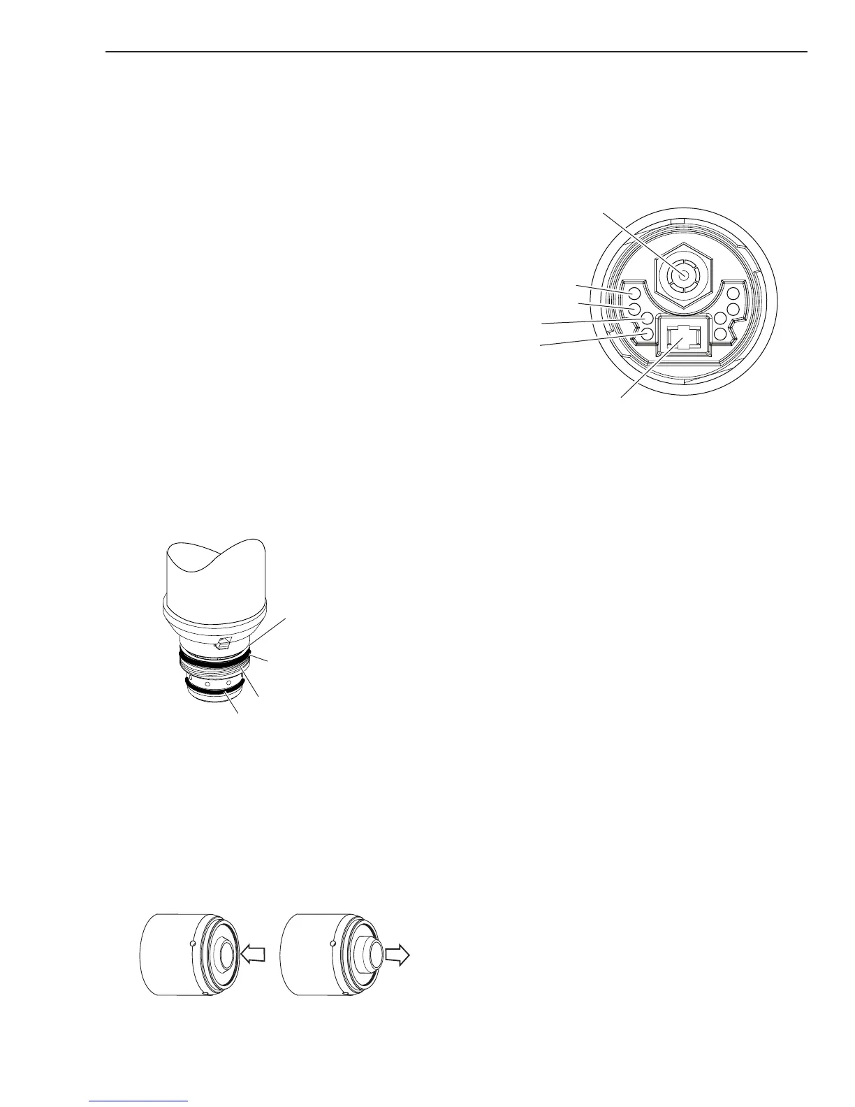
1. Upper O-Ring on torch head is in the wrong posi-
tion.
a) Remove shield cup from torch; check position
of the upper o-ring and correct if needed.
Upper Groove
with Vent Holes
Must Remain Open
Threads
Upper O-Ring
in Correct Groove
Lower O-Ring
Art # A-03725
2. Torch start cartridge is stuck.
a) Turn OFF power supply. Bleed down the sys-
tem. Remove the shield cup, tip,start cartridge
and electrode. Check the lower end unit of the
start cartridge for free movement. Replace the
cartridge if the lower end unit does not move
freely.
Art # A-08064_AC
Lower End Fitting
Full Compression
Spring-Loaded
Lower End Fitting at Reset /
Full Extension
3. Worn or faulty torch parts
a) Inspect torch consumables parts. Replace if
necessary.
4. Shorted Torch/leads
a) Disconnect torch from unit. With consumables
removed from the torch, check continuity of
torch at ATC, between negative/plasma lead
connection to pilot lead connection.
4 Torch Switch
3 Torch Switch
2 PIP
1 PIP
Pilot Lead
Art # A-08124
If a short is found, the problem is in the torch
and leads assembly. Remove the torch head
from the leads and check the leads and head
to determine which is defective.
5. Low primary input power or missing phase
a) Measure primary input voltage between L1,
L2 & L3 on W1 contactor under load.
6. Defective W1 contactor.
a) Check per section 5.11-C.
b) Check voltage into and out of W1 contactor
under load. Replace W1 if voltage drop is
found.
7. Shorted Sync cable connected between J14 on
Main PCB 1 to J9 on 40A PCB 5.
a) Check continuity.
8. Open connection between J12 on Main PCB 1 to
J1 on Capacitor PCB 2.
a) Check continuity.
9. Open connection between J2 on Capacitor PCB 2
to J3 on 40A PCB 5.
a) Check Continuity.
10. Open connection between J2 on Main PCB 1 to J1
on Logic PCB 3.
a) Check continuity.
11. Defective Logic PCB 3.
a) Measure Logic PCB 3 CUR_SET signal be-
tween J1-6 to TP1. If no voltage, replace PCB
3.
 Loading...


