CUTMASTER 40mm
INSTALLATION 3-2 Manual 0-5085
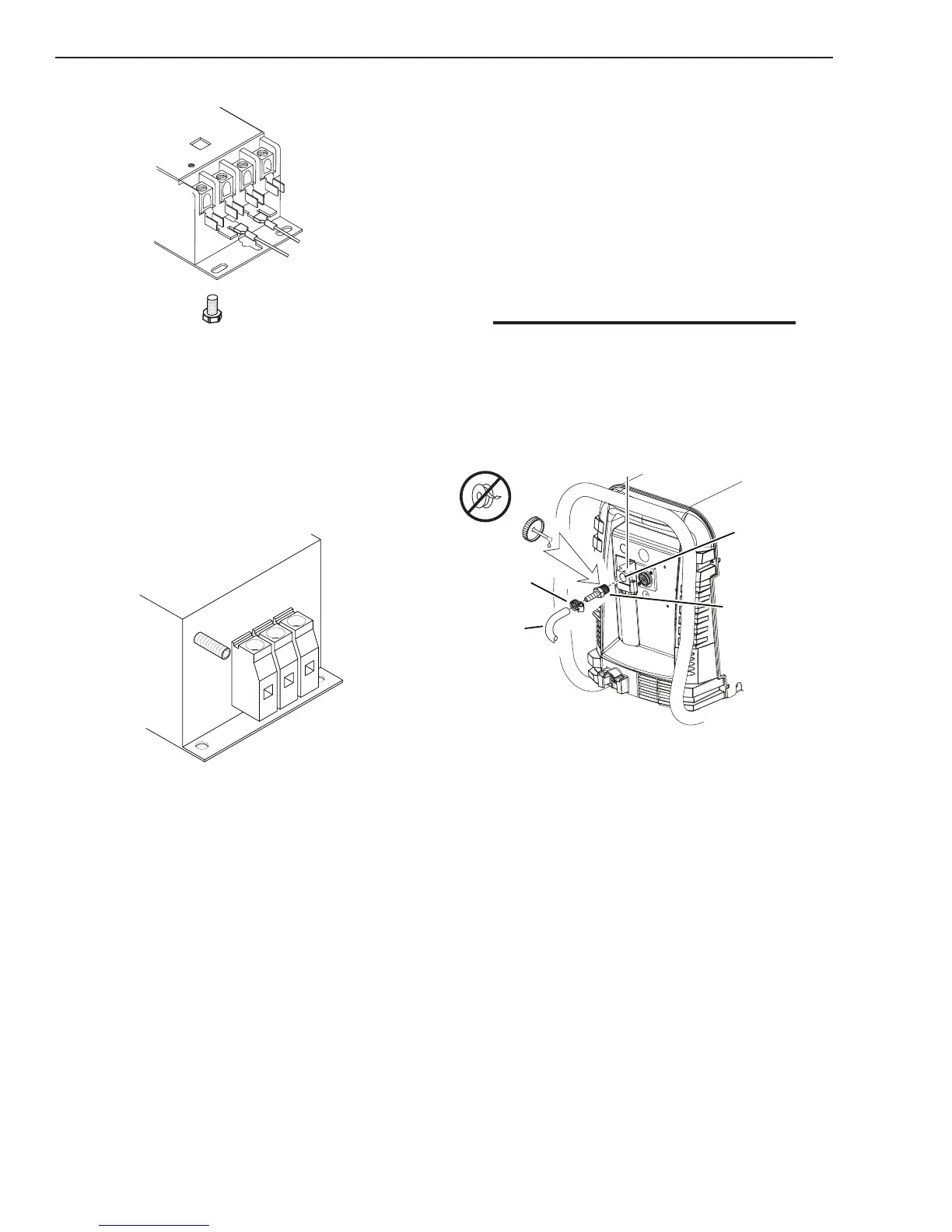
5. Connect the wires as follows.
For non CE units:
L4 L3 L2 L1
Art # A-08753
Ground
Terminal
Main
Contactor
• Three phase wires to L1, L2 and L3 on
the W1 contactor. It does not matter
what order these wires are attached. See
previous illustration and on label in the
power supply.
• Green / Yellow wire to Ground Termi-
nal.
For CE units:
GND
L1
L2
L3
EMC Input
Power Filter
Art # A-08752_AA
• ThreephasewirestoL1,L2andL3on
theCEInputPowerFilter.Itdoesnot
matterwhatorderthesewiresareat-
tached.Seepreviousillustrationandon
labelinthepowersupply.
• Green/YellowwiretoGround.
6. With a little slack in the wires, tighten the
strain relief to secure the power cable.
7. Reinstall the Power Supply cover per in-
structions found in section 5.
8. Connect the opposite end of individual
wires to a customer supplied plug and plug
into an appropriate input power receptacle.
(or connect directly to main disconnect)
9. Close the main disconnect switch to supply
power to the unit.
3.04 Gas Connections
Connecting Gas Supply to Unit
The connection is the same for compressed air or
high pressure cylinders. Refer to the following
two subsections if an optional air line lter is to
be installed.
1. Connect the air line to the inlet port. The
illustration shows typical ttings as an
example.
NOTE
For a secure seal, apply thread sealant to the
fitting threads, according to manufacturer's
instructions. Do not use Teflon tape as a thread
sealer, as small particles of the tape may break
off and block the small air passages in the torch.
Art # A-07943
Hose Clamp
Assembly
Inlet Port
Gas Supply
Hose
1/4 NPT or ISO-R
to 1/4” (6mm) Fitting
Air Connection to Inlet Port
 Loading...


