CUTMASTER 40MM
SERVICE 5-12 Manual 0-5085
5.07 Main Input and Internal Power
Problems
A. Primary input line fuse blows as soon as
primary disconnect is closed.
1. Primary input cable installed incorrectly.
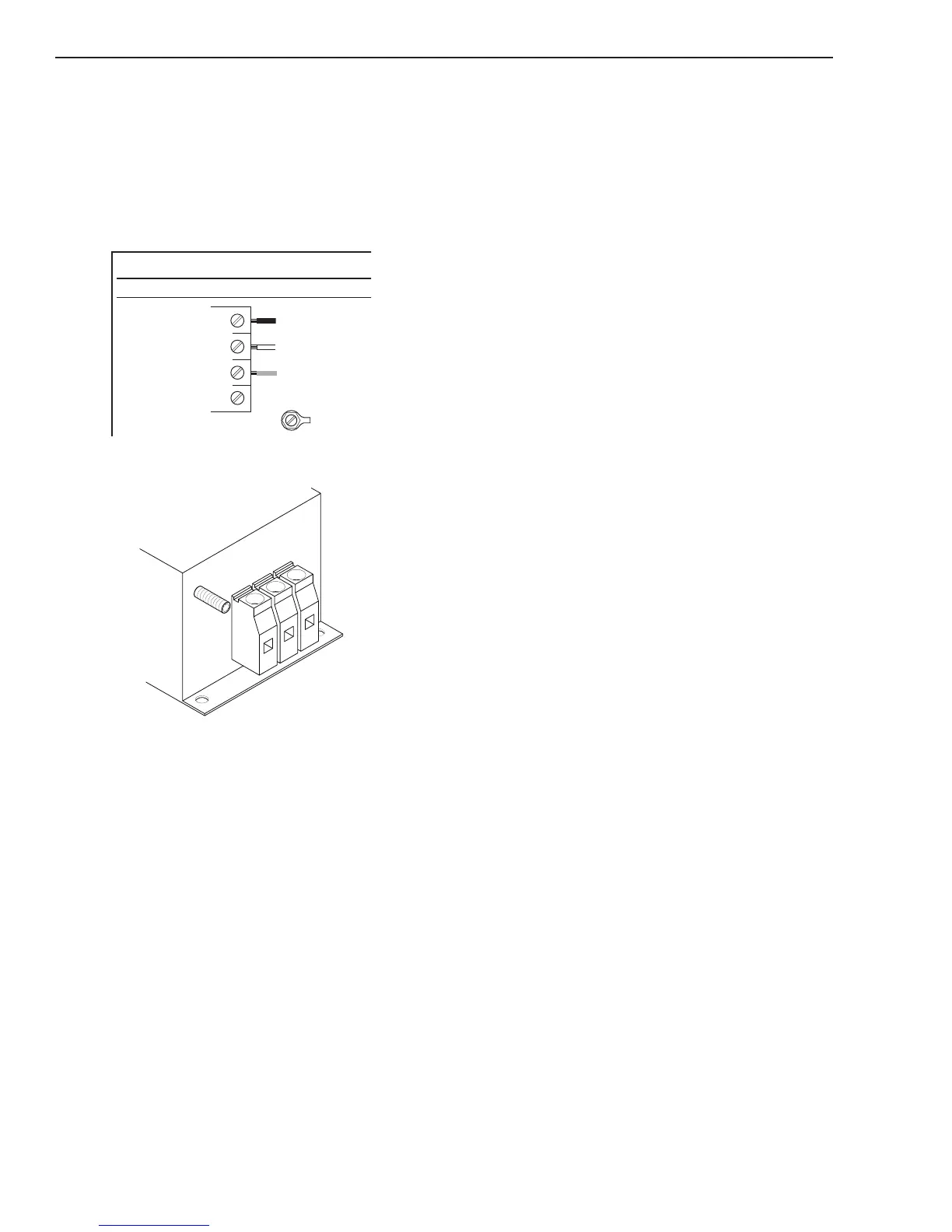
a) For Non EMC units - Check wiring of primary
power cable to the W1 contactor
Input Power Cable Connections
380-415 VAC Three-Phase (3ø)
GND
L1
L2
L3
L4
b) For EMC units - Check wiring of primary pow-
er cable to the EMC Filter terminal block.
GND
L1
L2
L3
EMC Input
Power Filter
Art # A-08752_AA
Three Phase Input Power Wiring
2. W1 contactor points are stuck closed
a) Check per section 5.11-A
3. Primary plug not wired correctly.
a) Check manufacturer's plug installation in-
structions.
4. Primary input cable is defective.
a) Check cable for shorts.
B. Primary line fuses blow immediately after
ON/OFF SWITCH (SW1) is turned to ON
position.
1. Shorted Input Diode Module
a) Check per section 5.11-B and 5.11-C
2. Shorted Input Capacitor PCB 2
a) Check per section 5.11-D
C. Gas flows with ON/OFF SWITCH in OFF
position
1. Foreign debris has lodged in gas solenoid.
a) Replace gas solenoid. This is a problem caused
by improperly filtered air supply. Customer
needs to add filtration to air supply prior to
unit inlet.
D. All front panel indicators are OFF, Fan
MOT 1 never turns ON. Main Contactor
W1 does not close.
1. Primary power not connected.
a) Check that cable is connected to primary
power.
2. Primary line fuse/breaker is blown/tripped.
a) Replace fuse or reset breaker.
3. Defective ON/OFF SWITCH
a) Check continuity
4. Defective Main PCB 1
a) Measure Main PCB power supply voltages at
the following test points
GND1 to +12V = 12VDC
GND1 to +48V = 48 VDC
Replace Main PCB 1 if not correct
5. Defective Ribbon Cable
a) Check continuity
6. Defective Logic PCB 3
a) Replace Logic PCB 3
E. AC LED ON, W1 contactor does not
energize. (In earlier revision units, the fan
MOT 1 will come ON after approximately
20 seconds)
1. Defective contactor.
a) Measure for 24VAC between wires 5 & 6. If
voltage is present, replace W1.
2. Defective Logic PCB 3.
a) Measure /W1_ON signal on Logic PCB 3 be-
tween J1-9 to TP1. Voltage should be 12VDC
then drop to less than 1VDC, 2 seconds after
turning SW1 to ON.
 Loading...


