CUTMASTER 40MM
Manual 0-5085 5-3 SERVICE
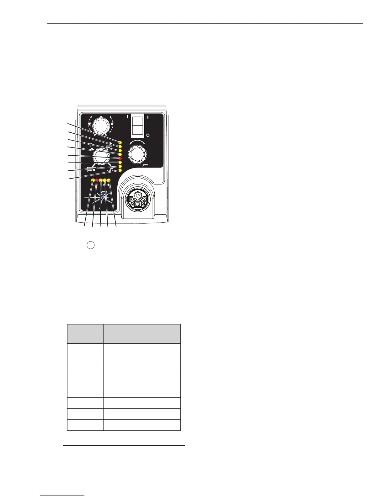
5.04 Fault Indicator
At initial power up, two lights will temporarily illumi-
nate for 2-3 seconds to show the version of software used.
To determine the first digit, count the function indicators
left to right, 1 through 5. To determine the second digit
count the pressure indicators, reading from bottom to
top, 0 through 7. In the example below the Temp indica-
tor and 75 psi indicators are on indicating the version
would be 2.3.
A
+
PSI BAR
MAXMAX
MINMIN
!
1
2
3
4
Art# A-07988
MIN
MAX
0
1
2
3
4
5
6
7
5
When the
"Fault" indicator is ON or blinking it
will be accompanied by one of the pressure indica-
tor lights depending on what the Fault is. Only one
of these faults will be displayed at one time. If more
than one fault exists, when the first fault is corrected
and cleared, the next fault will then be displayed. It
is possible to have a fault indicated in the function
indicators and another fault indicated in the pres-
sure indicators. The following table shows each of
the Faults possible.
Pressure
Indicator
Fault
Max OverPressure
90 Internal Error
85 ShortedTorch
80 Consumables Missing
75 StartError
70 Parts in Place
65 InputPower
Min UnderPressure
NOTE
Fault explanations are covered in the basic trouble-
shooting guide later in this chapter.
Explanation of Faults
UNDER PRESSURE: Indicates that operating pres-
sure is set too low and power supply output
power will be disabled.
INPUT POWER: Indicates primary line voltage is out-
side the operating limits of the power supply.
PART IN PLACE: Indicates that the shield cup is not
properly installed or tightened.
START ERROR: Indicates that the START SIGNAL
was active (ie. Torch Trigger depressed, hand
held pendant switch on or CNC signal for torch
on) during one of three (3) conditions:
1) During initial power up when ON/OFF
switch is turned to ON position
2) When fault which had been disabling the
system is cleared.
3) When the FUNCTION CONTROL SWITCH
Mode is moved from SET position to any of
the other three (3) modes of operation.
CONSUMABLES MISSING: Indicates that the elec-
trode, start cartridge or tip is missing or exces-
sively worn.
SHORTED TORCH (OUTPUT FAULT): This indicator
has two modes of operation:
First is the latched Fault mode. The 85 PSI LED blinks
at 1 cycle per second, indicating that one of two
fault conditions exist.
1) A shorted condition in the torch, leads or
consumables.
2) Low or no output voltage from the inverter
circuits.
In both cases, to reset the machine, turn the unit OFF,
identify and clear the problem and turn back ON.
The second mode is a non-latched mode. The 85 PSI
LED blinks at 5 cycles per second, indicating one
of three fault modes exists:
1) While using an Automation Torch at current
settings above 45 amps, the tip has contacted
the work piece
2) Air restriction in torch resulting in low voltage
during pilot.
3) Low voltage during cutting due to torch or
consumable problem.
In all three cases, to reset the machine, remove the
START signal.
INTERNAL ERROR: Indicates a microprocessor error.
 Loading...


