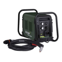
CUTMASTER 40MM
Manual 0-5085 5-19 SERVICE
2. Measure for 12VDC on the Logic PCB 3 between
J7-1 to J7-1 after the START signal is activated. If
voltage is not present replace Main PCB 1.
H. Fan MOT 1 does not turn ON after START
signal is activated. (MOT 2 & MOT 3 do
turn ON)
1. Defective Main PCB 1
a) Turn SW1 to OFF position. Turn SW1 back to
ON position and measure for 12VDC between
J7-1 to J7-2 before START signal is activated.
If no voltage is present, replace Main PCB 1.
2. Defective MOT 1
a) Check to be sure there is no physical obstruc-
tions preventing MOT 1 fan blades from turn-
ing. Replace MOT 1.
I. Either MOT 2 or MOT 3 do not turn ON
after START signal is activated.
1. Fan wires not connected to 40A PCB 5
a) Check and reconnect to 40A PCB 5.
2. Defective fan.
a) Check to be sure there is no physical obstruc-
tions preventing fan blades from turning.
Replace respective fan.
J. Fans MOT 2 & MOT 3 do not turn ON after
START signal is activated.
1. Open connection between Main PCB 1 J13 to 40A
PCB 5 J4.
a) Verify connectors are plugged in. Check con-
tinuity .
b) Measure voltage at J4-2 to J4-10 on 40Amp
PCB 5 for 12VDC. The voltage should drop
to less than 2VDC after a START signal is ac-
tive. If the 12VDC is not present or does not
drop to less than 2VDC after a START signal
is activated, then replace the ribbon cable.
2. Defective 40AMP PCB 5
a) Measure the voltage between J1-1 to J1-2 on
the 40AMP PCB 5 for 12VDC after the START
signal is activated. If 12VDC is present replace
40AMP PCB 5.
3. Defective Fans MOT 2 and 3.
a) If 12VDC is present on J1 and J2 connectors
on 40A PCB 5, replace fans MOT 2 & MOT 3.
5.09 Main Arc and Controls
Problems
A. Main arc will not establish, LED D59 on
Main PCB remains ON while pilot arc is
striking the work piece.
1. Work Cable not connected.
a) Connect cable to work piece
2. Work cable open / broken.
a) Check continuity of work cable. Insure con-
nection of cable to clamp is secure.
B. When Pilot Arc is brought to the work
piece, the arc goes out immediately or
extinguishes while cutting. ERROR
indicator and 85 PSI indicator flashing.
a) Ferrite filter on ribbon cable between J1 on Logic
PCB 3 to J2 on Main PCB 1 is broken, loose or
missing.
b) Ferrite on wire harness between J13 connector
on Main PCB 1 to J4 connector on 40A PCB 5 is
broken, loose or missing.
c) Wires SEC1 and SEC2 routed to close to compo-
nent U2 on 40A PCB 5. Re-route to space a least
1 inch (25mm) away.
d) Older revision 40A PCB 5. Replace if PCB 5 revi-
sion is "AC" or earlier.
C. Main arc transfers but current cannot be
adjusted.
1. Defective Logic PCB 3.
a) While main arc is transferred,measure volt-
age on Main PCB between test points GND1
to I_DMD1.
b) Adjust CURRENT CONTROL POTENTIOM-
ETER from maximum to minimum. Voltage
should vary from 4VDC at max to 1 VDC at
min
If voltage does not vary with CURRENT CONTROL
POTENTIOMETER, replace Logic PCB 3.
2. Defective Main PCB 1.
a) Replace Main PCB 1.
D. In LATCH mode, when the START signal is
released the arc shuts OFF immediately.
1. Defective Logic PCB 3
a) Replace Logic PCB 3
 Loading...


