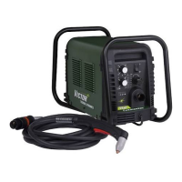
CUTMASTER 40MM
SERVICE 5-18 Manual 0-5085
b) Measure Logic PCB 3 for SHDN signal be-
tween J1-10 to TP1. Normally 12VDC signal
should drop to less than 1VDC when START
signal is active. If voltage does not drop, re-
place PCB 3.
c) Measure Logic PCB 3 Signal /400_IN between
J1-4 to TP1 for less than 2VDC.
If signal measures 12 VDC, replace the Logic
PCB 3
12. Defective Main PCB 1.
a) Measure for approximately 325VDC on Ca-
pacitor PCB 2 between MTH 1 to MTH 7 under
load. If voltage is not present replace PCB 1.
13. Defective Capacitor PCB 2.
a) Disconnect plug from J2 on Capacitor PCB 2
and measure between J2-1 to J2-2 for 12VDC.
If voltage is low or zero, replace PCB 2.
14. Defective 40Amp PCB 5.
a) Isolate the 40A PCB 5 by disconnecting plug
from J4, the Sync cable from J9 and the wire
from terminal CHOKE1. Supply a START
signal. If the FAULT is cleared, replace PCB
5.
15. Defective Main PCB 1.
a) Replace PCB 1.
C. SHORTED TORCH FAULT. FAULT
indicator and 85 PSI LED are flashing at 5
cycles per second.
This mode is a non-latched mode.
1. While using an Automation Torch at current set-
tings above 45 amps, the tip has contacted the
work piece.
a) Check standoff height
2. Air restriction in torch resulting in low voltage
during pilot.
a) Check torch consumables for wear or debris.
3. Low voltage during cutting due to torch or con-
sumable problem.
a) Check torch consumables for wear or debris.
In all three cases, to reset the machine, remove the
START signal.
D. AC LED ON, TEMP LED OFF, GAS LED
ON, gas flowing, DC LED ON, Fault
Indicator OFF, No arc in torch.
1. Defective Main PCB 1.
a) Install jumper on Main PCB 1 between test
point GND1 to terminal TIP1.
b) Apply START signal. If Pilot starts, replace
Main PCB 1.
E. AC LED ON, TEMP LED OFF, GAS LED
ON, gas flowing, DC LED ON, Fault
Indicator OFF, Pilot Arc is intermittent.
1. Defective Main contactor W1.
a) Check W1 per Pre Power-UP checks.
2. Defective Logic PCB 3
a) Measure for 12VDC on Main PCB between
test Point GND1 to J2-8. If 12VDC is present,
replace Logic PCB 3.
3. Defective Main PCB 1.
a) Replace Main PCB 1.
F. INTERNAL ERROR. Fault Indicator and 90
PSI Indicators are flashing.
1. There has been a microprocessor problem.
a) Turn ON/OFF SWITCH to OFF position and
then turn to ON position to clear the error.
2. Defective Logic PCB 3.
a) Replace Logic PCB 3.
G. Fans MOT 1-3 do not turn ON after a
START signal is activated.
1. Defective Logic PCB 3.
a) Measure voltage at J1-14 to J1-25 on Logic PCB
3 for 12VDC. The voltage should drop to less
than 2VDC after a START signal is active. If the
voltage remains at 12VDC replace the Logic
PCB 3.
NOTE
When the unit is turned ON the cooling fans MOT
1-3 will remain OFF. (In earlier units MOT 1 will turn
ON for one (1) second and then turns OFF) The fans
will turn ON when a START signal (Torch Switch,
Remote Pendant switch, or CNC START) is active
and will remain ON for ten (10) minutes after the
START signal is removed. If an over temperature
condition occurs, the fans will continue to run while
the condition exists and for a ten (10) minute period
after the condition is cleared.
 Loading...


