CUTMASTER 40mm
PARTS REPLACEMENT 7-8 Manual 0-5085
Optional Two-Stage Filter Element
Replacement
The Two-Stage Air Filter has two Filter Elements. When
the Filter Elements become dirty the Power Supply will
continue to operate but cut quality may become unac-
ceptable. Refer to Section 6, Parts List, for replacement
filter element catalog number.
1. Shut OFF primary input power.
2. Shut OFF air supply and bleed down system.
WARNING
Always turn OFF the air supply and bleed the
system before disassembling the Filter As-
sembly as injury could result.
3. Loosen the two bolts on the top of the Filter As-
sembly enough to allow the Filter Elements to
move freely.
4. Note the location and orientation of the old Filter
Elements.
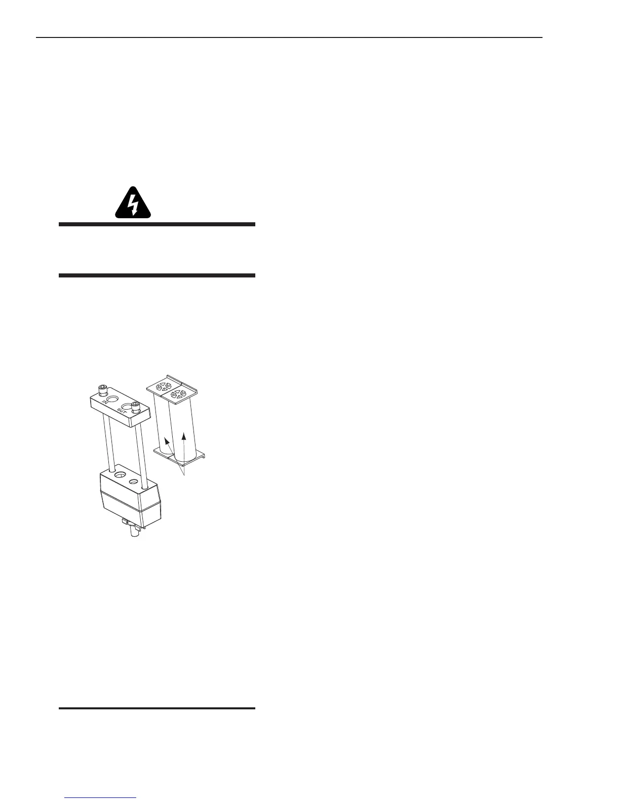
5. Slide out the old Filter Elements.
First & Second
Stage
Cartridges
(as marked)
Art # A-02942
Optional Two-Stage Filter Replacement
6. Slide the replacement Filter Elements into the
Filter Assembly, with the same orientation as
noted in Step 4 above.
7. Hand tighten the two bolts evenly, then torque
each bolt to 20 - 30 in-lbs (2.3 - 3.4 Nm). Improper
torque may damage the gasket.
8. Slowly apply air pressure to the assembly, check-
ing for leaks.
NOTE
A small amount of air leakage from the bottom
fitting is normal.
This completes the parts replacement procedures.
7.08 Right Side Internal Parts
Replacement
A. Capacitor PCB (PCB 2) Replacement
Tools required: T20 Torx Driver, #2 Phillips Head Driver
1. Remove the Cover per subsection 7.04-A.
2. Disconnect J1 & J2 from PCB 2.
3. Note the location and remove all wires connected
to PCB 2
4. Remove the fifteen (15) screws securing PCB 2
to the Main PCB and 40AMP PCB
5. Install the replacement PCB by reversing the
above steps.
B. Main PCB (PCB 1) Replacement
Tools required: T20 Torx Driver
1. Remove the Cover per subsection 7.04-A.
2. Remove Capacitor PCB per subsection 7.08-A
3. Remove the two large gas hoses per subsection
7.05-C.
4. Remove the Gas Solenoid per subsection 5.05-F.
5. Disconnect the wires and connectors from the
PCB, noting the location and orientation of each
wire and connector.
6. Remove the four (4) mounting screws securing
the PCB to the center chassis.
7. Carefully guide the PCB assembly up and out of
the unit.
8. Install the replacement PCB by reversing the
above steps.
9. Reinstall the power supply cover
 Loading...


