CUTMASTER 40mm
Manual 0-5085 7-7 PARTS REPLACEMENT
6. Disconnect the input line from the filter element
assembly.
7. Remove the filter element assembly through the
rear opening.
NOTE
If replacing or cleaning just the filter element
refer to the following illustration for disas-
sembly.
Art # A-07990
Filter Element
8. Install the new or cleaned assembly by reversing
these procedures.
9. Turn ON the air supply and check for leaks before
reinstalling the cover.
B. Input Power Cable Replacement
Tools required: Phillips Head Screwdriver, Flathead
Screwdriver,
1. Remove the Cover per subsection 7.04-A.
2. Disconnect the input cable wires from the W1
contactor terminals and ground lug.
(For CE units: Disconnect input cable from the CE
Input Power Filter terminals and ground lug.)
3. Loosen the two screws in the cable strain relief
4. Remove cable through the rear panel.
5. Install replacement Input Power Cable by revers-
ing above steps.
6. Reinstall the power supply cover
D. Optional Single-Stage Filter Element
Replacement
These instructions apply to power supplies where the
optional Single-Stage Filter has been installed.
The Power Supply shuts down automatically when
the Filter Element becomes completely saturated. The
Filter Element can be removed from its housing, dried,
and reused. Allow 24 hours for Element to dry. Refer
to Section 6, Parts List, for replacement filter element
catalog number.
1. Remove power from power supply.
2. Shut OFF air supply and bleed down system
before disassembling Filter to change Filter Ele-
ment.
3. Disconnect gas supply hose.
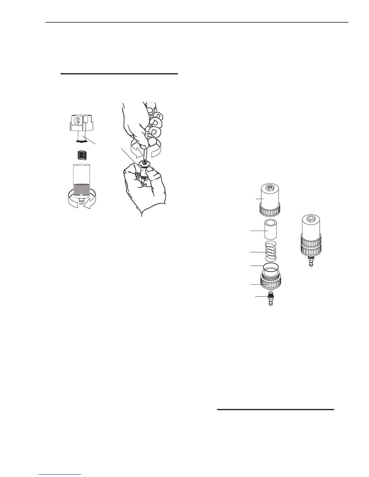
4. Turn the Filter Housing Cover counter-clockwise
and remove it. The Filter Element is located
inside the Housing.
Art # A-02476
Filter
Element
(Cat. No. 9-7741)
Housing
Cover
Barbed
Fitting
Spring
Assembled Filter
O-ring
(Cat. No. 9-7743)
Optional Single-Stage Filter Element Replacement
5. Remove the Filter Element from the Housing and
set Element aside to dry.
6. Wipe inside of housing clean, then insert the
replacement Filter Element open side first.
7. Replace Housing on Cover.
8. Reattach gas supply.
9. Reinstall the power supply cover
NOTE
If unit leaks between housing and cover,
inspect the O-ring for cuts or other damage.

 Loading...


