CUTMASTER 40MM
Manual 0-5085 5-21 SERVICE
2. Retest continuity between terminals while engag-
ing the contacts manually. This can be done by
pushing down on the recessed actuator button on
the top of W1 or pushing down on the actuator
arm on the side of W1.
L1 to T1
L2 to T2
L3 to T3
L4 to T4
The contacts should be closed – Continuity
3. Visually check W1 contact points. To take the
cover OFF, remove the two cover screws shown
in the previous illustration. If contacts are stuck
together or show excessive arcing or pitting, re-
place W1.
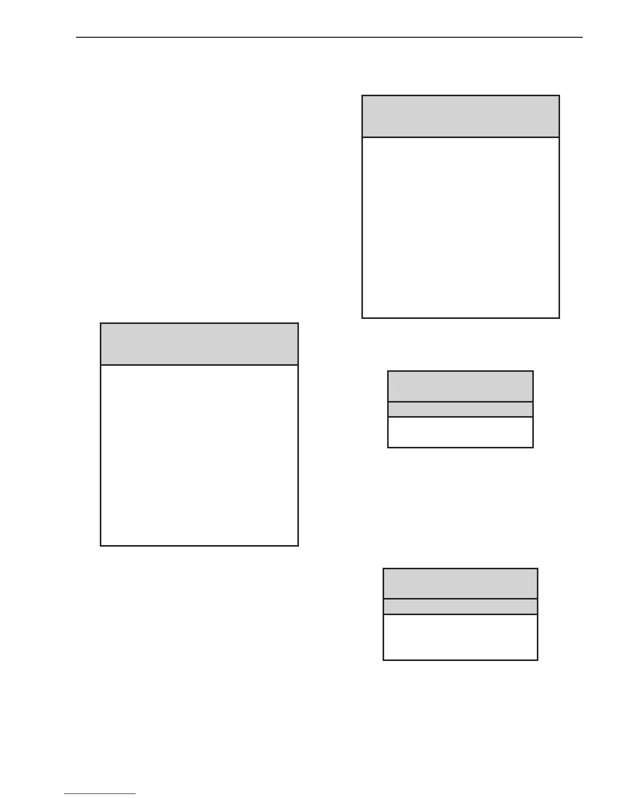
B. PCB 1 Input Diode D1 Test
1. Using an ohmmeter perform the tests in the
chart:
Input Diode Module D1 on PCB 1
Test points located on PCB 2
Meter (+) Meter (-) Indication
80A_AC1 MTH 1 Forward Biased Diode
80A_AC2 MTH 1 Forward Biased Diode
80A_AC3 MTH 1 Forward Biased Diode
MTH 1 80A_AC1 Reverse Biased Diode
MTH 1 80A_AC2 Reverse Biased Diode
MTH 1 80A_AC3 Reverse Biased Diode
MTH 7 80A_AC1 Forward Biased Diode
MTH 7 80A_AC2 Forward Biased Diode
MTH 7 80A_AC3 Forward Biased Diode
80A_AC1 MTH 7 Reverse Biased Diode
80A_AC2 MTH 7 Reverse Biased Diode
80A_AC3 MTH 7 Reverse Biased Diode
MTH 7 MTH 1 2 Forward Biased Diodes
C. PCB 5 Input Diode D1 Test
1. Using an ohmmeter perform the tests in the
chart:
Input Diode Module D1 on PCB 5
Test points are located on PCB 2
Meter (+) Meter (-) Indication
40A_AC1 PMTH 1 Forward Biased Diode
40A_AC2 PMTH 1 Forward Biased Diode
40A_AC3 PMTH 1 Forward Biased Diode
PMTH 1 40A_AC1 Reverse Biased Diode
PMTH 1 40A_AC2 Reverse Biased Diode
PMTH 1 40A_AC3 Reverse Biased Diode
PMTH 4 40A_AC1 Forward Biased Diode
PMTH 4 40A_AC2 Forward Biased Diode
PMTH 4 40A_AC3 Forward Biased Diode
40A_AC1 PMTH 4 Reverse Biased Diode
40A_AC2 PMTH 4 Reverse Biased Diode
40A_AC3 PMTH 4 Reverse Biased Diode
PMTH 4 PMTH 1 2 Forward Biased Diodes
D. PCB 2 Capacitor / Relay Test
1. Using an ohmmeter perform the tests in the
chart:
INPUTCAPACITORS
PCB 2
Meter + Meter - Indication
MTH2 MTH4 Charging
MTH8 MTH7 Charging
Most meters will show a charging action. Initially a
low resistance will be shown and then the resistance
will start to increase. If the meter probes are reversed
the reading will decrease to zero, then start charging
in the opposite polarity.
2. Using an ohmmeter perform the tests in the
chart:
INPUTVOLTAGESELECTIONRELAYS
PCB 2
Meter + Meter - Indication
MTH7 MTH4 Charging
MTH8 MTH2 Charging
MTH8 MTH4 Charging
 Loading...


