Electrical Maintenance 8-14
NOTE: The alternator field fuse (F15 on uP-VI and TG-VI, F7 on uP-IV and F4 on SR-2/SR-3) must be removed on the relay
board on units equipped with the Prestolite alternator. If this fuse is inserted in the relay board, the alternator will not function
properly.
1. Set the unit for CONTINUOUS operation and place the main On-Off switch in the OFF position.
2. Check the battery voltage. If the battery voltage is less than 12 volts, the battery must be charged or tested to determine if it
should be replaced.
3. Check the voltage at the B+ terminal on the alternator. Battery voltage must be present. If not, check the 2A circuit.
4. Disconnect the alternator harness from the voltage regulator by carefully pushing on the spring clip to release the plug lock.
5. Set the unit for CONTINUOUS operation and place the main On-Off switch in the ON position. If possible, enter Service
Test Mode High Speed Cool (HSC) before the Unit starts. Refer to the appropriate Diagnostic’s Manual for specific
Information on Service Test Mode.
6. Check the voltage at pin A and pin B in the two pin connector on the alternator harness.
a. The A pin is the battery sense circuit and should be at battery voltage. If not, check the sense circuit (2 or equivalent) in the
alternator harness and in the main wire harness.
b.The B pin is the excitation circuit and should be at 10 volts or higher. If not, check the excitation circuit (7K or equivalent)
in the alternator harness and in the main wire harness.
7. If battery voltage is present on the sense and excitation circuits, connect the alternator harness to the voltage regulator.
Note:The Current through the L Terminal must be limited through a 300ohm resistor in the EXC or 7-circuit. (Like the bosch
Alternator). The Alternator will be damaged if +12V is connected directly to the L Terminal.
The Nominal Voltage regulator setting for Thermo King Alternators is 14.15 +/- 0.20 @ 25’C)
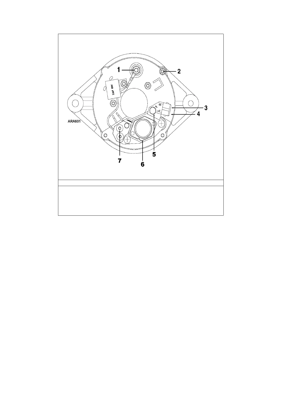
Check Points for Bosch Alternator Test
1. B+ Terminal (Positive Output - 2A Wire)
2. B- Terminal (Negative Ground - CH Wire)
3. S Terminal
4. L Terminal
5. F2 Terminal (Do not Ground)
6. Voltage Regulator and Brush Assembly
7. W Terminal (AC Output - W wire)
 Loading...