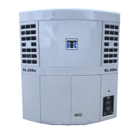
Specifications 3-8
ELECTRICAL CONTROL SYSTEM
Voltage:
All models 12.5 Vdc (nominal)
Battery
Wet Cell
EON
12 Vdc, AHr Rating - 92AHrs, 760 Cold Cranking Amps at
-18 C
12.8 Vdc Nominal, AHr Rating - 65AHrs, 880 Cold
Cranking Amps at -18 C
TG-VI, µP-IV, µP-V, µP-VI and SR-2 Controllers:
2 Circuit:
SL, SLe models 40 ampere fuse
High Speed Solenoid Circuit:
SL/ SLe models 15 ampere fuse
8 or 8F Circuit:
SL/ SLe (except SL-400 and SL-400e) 15 ampere fuse
SL-400 and SL-400e models 25 ampere fuse
Damper Circuit:
SL/ SLe models 15 ampere fuse
Remote Evaporator Fan (RFM) Circuit:
TCI and SPECTRUM models 25 ampere fuse
Other Circuits*:
SL/ SLe 2 or 3 ampere fuses
Fusible Link:
All models 16 gauge wire (100 to 110 amperes)
Evaporator Fan Circuit Breaker:
SL TCI and SPECTRUM SL 30 ampere auto reset
Battery Charging Alternator:
All models (Except TCI and SPECTRUM models) 37 ampere brush type (optional: 65 ampere brush type)
SL TCI and SPECTRUM 120 ampere brush type
Voltage Regulator Setting:
All models 13.8 to 14.2 @ 25 C
Alternator/Regulator LED Diode
Used when replacing “Old Style” Integral Regulator
Alternators with “New Style” Remote Regulator
Alternators
4.7 mFd 50 Vdc
Alternator/Output Capacitor
Used to Filter Electrical Interference on “Old Style”
Integral Regulator Alternators
0.5 mFd 100 Vdc
* The alternator field fuse (F15 or F7) must be removed from the relay board for the Bosch alternator.
SLXi/SLXe/SLX/SL-400 SR-2/SR-3 Controller
Fuse Size Function
F2 15A 2AB Power
F3 40A Fuel Sol Pull-In/Starter Circuit
F4 None No Fuse - all Bosch Alternators
F5 60A Preheat Circuit (Slow Burn Fuse)
F6 15A High Speed Circuit
F7 2A 8FP Circuit - CAN Bus
F8 5A CAN Connector J12
F9 5A CAN Connector J14
F10 10A 8X Power (Install Fuse in Upper Position)
F11 10A Zone 1 LLS (SPECTRUM)
F12 5A CAN Connector J13
F13 2A 8FC Circuit (Remote Lights)
F15 p/s On/Off Relay
F20 2A Alternator Sense
F25 7.5A HPCO Switch Circuit

 Loading...


