Engine Maintenance 9-19
3. Adjust the following unit switches if they are provided on your unit:
• Place the Diesel-Electric switch in the DIESEL position.
• Place the Cycle-Sentry switch in the CONTINUOUS RUN position.
• Place On-Off switch(es) in the ON position.
4. Check the voltage on 8D circuit in the main wire harness connector for the fuel solenoid. Refer to the illustrations on the
previous page to identify the pins in the wire harness and fuel solenoid connectors.
a. If battery voltage is not present on the 8D circuit, check the 8D circuit and related components for a fault.
b.If battery voltage is present on the 8D circuit, go to step 6.
5. Check CH circuit in the main wire harness at the fuel solenoid connector for continuity to a good chassis ground.
a. If there is no continuity between CH circuit and a good chassis ground, check the CH wire for an open circuit.
b.If there is continuity between CH circuit and a good chassis ground, go to step 7.
6. Place a jumper wire between the CH circuit in the connector on the fuel solenoid and a good chassis ground.
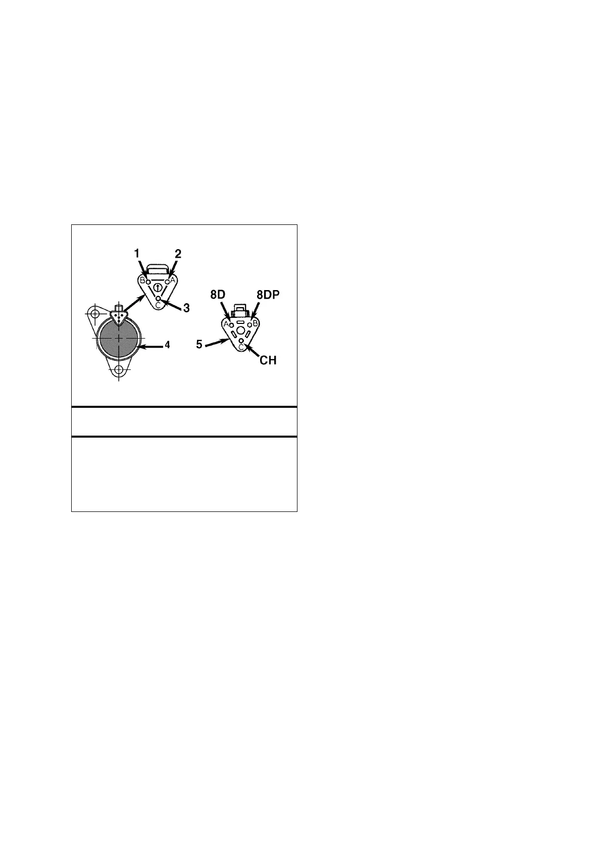
Integral Fuel Solenoid Harness Connections – TK 482,
TK 486 and TK 486V Engines
1. Pin B: White (8DP) Wire
2. Pin A: Red (8D) Wire
3. Pin C: Black (CH) Wire
4. Fuel Solenoid and Connector
5. Main Wire Harness Connector and Pins:
Pin A = 8D
Pin B = 8DP
Pin C = CH
 Loading...