Thermo Scientific TSQ Series Hardware Manual 13
Functional Description
This chapter describes the principal components of the TSQ system and their respective
functions.
A functional block diagram of the TSQ mass spectrometer is shown in Figure 5. A sample
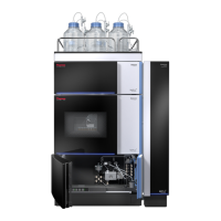
transfer line connects the LC to the mass spectrometer. The autosampler and LC are usually
installed on the left of the mass spectrometer. The syringe pump and divert/inject valve are
integrated into the mass spectrometer cabinet.
In a typical analysis, a sample can be introduced in any of the following ways:
• Using the syringe pump (direct infusion)
• Using the divert/inject valve fitted with a loop and an LC (flow injection analysis)
• Using a divert/inject valve and LC fitted with a column (LC/MS)
In analysis by LC/MS, a sample is injected onto an LC column. The sample then separates
into its various components. The components elute from the LC column and pass into the
mass spectrometer where they are analyzed.
The Electrospray (ESI), heated electrospray (H-ESI), nanospray (NSI), atmospheric pressure
photo ionization (APPI), and atmospheric pressure chemical ionization (APCI) techniques
each ionize sample molecules at atmospheric pressure. The ion optics focus and accelerate the
resulting sample ions into the mass analyzer where they are analyzed according to their
mass-to-charge ratios. An ion detection system then produces a signal proportional to the
number of ions detected. The system electronics receive and amplify the ion current signal
from the ion detection system. That signal is then passed on to the data system for further
processing, storage, and display. The data system provides the primary TSQ mass
spectrometer user interface.
Contents
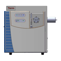
• Autosampler (optional)
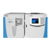
• Liquid Chromatograph (optional)
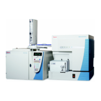
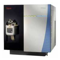
• Mass Spectrometer
• Data System
 Loading...