1
Introduction
Electronic Assemblies
Thermo Scientific Orbitrap Fusion Series Hardware Manual 5
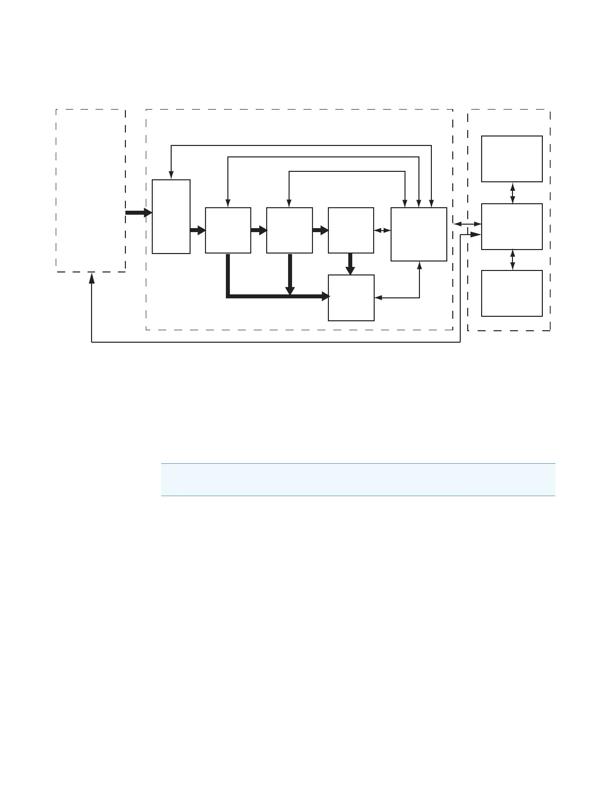
Figure 1. Functional block diagram of the Orbitrap Fusion Series MS
Electronic Assemblies
The electronic assemblies that control the operation of the mass spectrometer are distributed
among various printed circuit boards (PCBs) and other modules, in the embedded computer,
and on or around the vacuum manifold of the mass spectrometer. You cannot service the
electronic assemblies.
Controls and Indicators
This section describes the following controls and indicators for the Orbitrap Fusion Series
MS:
• LEDs
• Power Entry Module
• Communications Panel
Ion
optics
Mass
analyzers
Ion
detection
system
Instrument
control
electronic
assemblies
Vacuum
system
Printer
Computer
Monitor
Mass spectrometer Data systemInlet
Autosampler
(optional)
LC pump
(optional)
Syringe pump
Divert/inject
valve
API
source
Note If you need assistance, contact your local Thermo Fisher Scientific field service
engineer.

 Loading...


