THRUSH AIRCRAFT, INC – MODEL S2R-G10
AIRCRAFT MAINTENANCE MANUAL
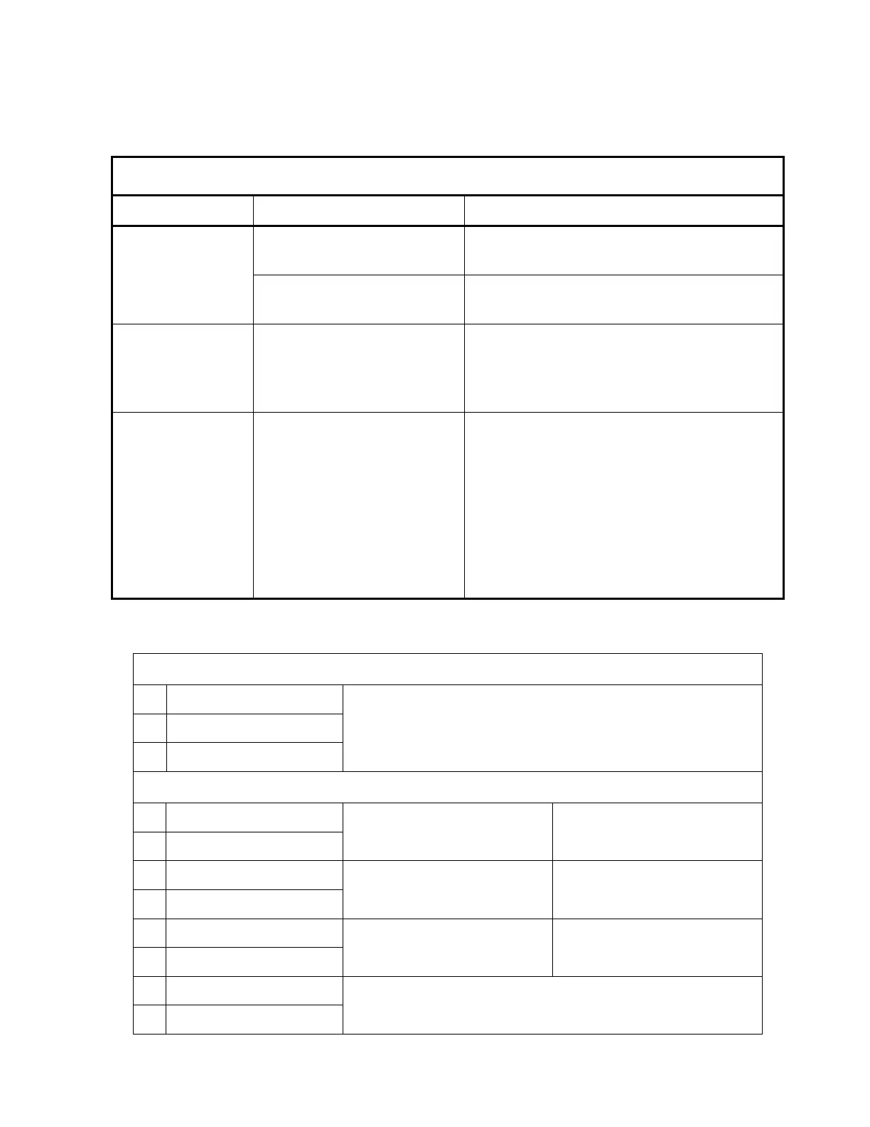
INSTRUMENT TROUBLE SHOOTING CHART, Table 8-1, Page 5
HOPPER QUANTITY SYSTEM (OPTIONAL EQUIPMENT)
PROBLEM PROBABLE CAUSE REMEDY
Bad sensing element
Disconnect wires and check resistance.
Refer to Table 8-2.
No indication on
indicator
Resistance check bad. Replace
element (non-repairable).
No indication
and resistance
checked good
Bad indicator
Check power and ground connections.
Observe meter on FA-A control unit. If
meter works with movement of ball,
indicator or wires to indicator are bad.
No indication
and resistance
checked good
Bad FA-A control
Check wiring. Wiring OK, replace FA-A
control. Pins 5, 8, 11 and 15 are power
pins on FA-A unit. Pin 15 is attached to
1A C/B. Pins 8 and 11 are jumped to
pin 15. Pin 5 goes to + on rear of tank
quantity gauge. Grounds are located on
pins 4 and 16. Pin 4 is connected to
ground on rear of tank quantity gauge.
Pin 16 is chassis ground.
Table 8-2: Hopper Level Sensor Calibration Chart
LEVEL SENSING UNIT
BLUE
BLACK
BROWN
WIRES COMING FROM TUBE
APPROXIMATE RESISTANCE WITH FLOAT IN CENTER OF TUBE
1. BLACK
BLUE
3000 – 5000 OHMS
2. BLACK
BROWN
2000 – 3000 OHMS
3. BROWN
BLUE
2000 OHMS
4. BLACK
BLUE
SMALLER OR EQUAL TO BLACK/BROWN PLUS
RESISTANCE BETWEEN BROWN/BLUE
Effective: 03/26/2010 Page 8-17