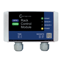
TD80™ Level Gauging and Overfill Prevention System Product Manual
Rev. 2, August 4, 2015/ TD80 and Overfill Prevention System Troubleshooting Page 75
3. Loss of SV Bus Communication, Finch Display shows “----”.
a. “----” displayed on the 5332(E) indicates loss of SV Bus communication with the TD80
transmitter. Any other Display such as “2 LO”, “E 20”, Spill or level confirms proper
communication with the transmitter.
b. If multiple
compartments
are displayed on
one 5332(E),
check all
compartment
positions on the
selector switch
i. If all positions are inactive, check the
wiring from the switch to the SV Bus input
on the 5332(E) and common power
supply wiring to the TD80 transmitters.
Inspect for broken or corroded
wiring and repair as necessary.
ii. If one or more compartments; but not all
are inactive, then troubleshoot the
Transmitter and wiring to the selector
switch.
Inspect for broken or corroded
wiring and repair as necessary.
c. Check the SV
Bus LED on the
5332(E) for
activity. Blinking
fully on and fully
off indicates
normal bus
voltages. The
LED will blink in
bursts every
second as the
level information
is transmitted to
the Display.
i. Partially on or
off indicates a
defective TD80
system
component, loss
of power to a
TD80 system
component or
an SV Bus short
circuit to either
power or
ground.
a. Use the test light to
check for power and
ground to the TD80
system components
on the SV Bus. Check
at the power and
ground terminals as
well as any
intermediate
connections such as
junction boxes, plugs
and sockets.
Inspect for broken or corroded
wiring where the test light fails
to illuminate and repair as
necessary.
b. SV Bus LED
partially on indicates
short circuit to power
Troubleshoot SV Bus and
repair or replace as necessary
c. SV Bus LED
partially off indicates a
short circuit to ground.
Troubleshoot SV Bus and
repair or replace as necessary
d. If the SV Bus LED is
off continuously
i. Check for power and ground
to the TD80 Transmitter
ii. Clip the test light to ground
and probe the SV Bus signal
wire. Tap the probe tip on an
SV Bus terminal and the LED
will blink with each tap to
indicate continuity through the
wiring and SV Bus receiver in
the 5332(E). Probe at each SV
Bus circuit point until the open
circuit or defective component
is isolated.
e. If the SV Bus LED is on continuously, check for a short
circuit to ground on the SV Bus. This can be done by
disconnecting the devices from the SV Bus, clip the test
light to battery power and probe for ground on the SV
Bus at each circuit point until the short circuit or defective
component is isolated.

 Loading...