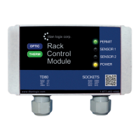
TD80™ Level Gauging and Overfill Prevention System Product Manual
Page 80 TD80 and Overfill Prevention System Troubleshooting/ Rev. 2, August 4, 2015
10. Overfill Prevention System fails to stop loading on high level alarms.
i. Ensure that HH and Spill/Fail alarms activate, TD80 system is operating normally.
ii. Deactivate/reset the alarms for further troubleshooting.
iii. Check for power at Relay Module Solenoid
terminal
1. If power is present, check wiring to
solenoid for a short circuit to power.
2. If power is not present, check solenoid
valve.
3. Energize and de-energize solenoid by
moving J10 jumper to check for solenoid
and valve operation. This also checks for a
shorted 5332E FAIL-NC (or SPILL/FAIL-NC
on 5332E/PS Display) to FAIL-COM (or
SPILL/FAIL-COM on 5332E/PS Display)
connection.
iv. Check for short circuit to ground at Relay Module HH-NC.
v. Check for short circuit to ground at 5332E HH-NC, HH-COM and FAIL-NC (or SPILL/FAIL-
NC on 5332E/PS Display).
vi. Inspect for defective, incorrect or corroded wiring and repair as necessary
i. Ensure that HH and Spill/Fail alarms activate, TD80 system is operating normally.
ii. Deactivate/reset the alarms for further troubleshooting.
iii. Check that the LED to fiber optic cable is OFF
iv. If the LED is OFF, then troubleshoot the P2000
v. If the LED is ON, then troubleshoot the 5332E HH and FAIL relay fault or shorted wiring.
vi. Inspect for defective, incorrect or corroded wiring and repair as necessary
11. Overfill Prevention System fails to stop loading when PTO signal is off.
i. Ensure that HH and Spill/Fail alarms activate, TD80 system is operating normally.
ii. Deactivate/reset the alarms for further troubleshooting.
iii. Energize and de-energize solenoid by moving J10 jumper to check for solenoid and valve
operation.
iv. Ensure that the 5332E Displays “OFF” when the PTO signal is disengaged.
v. If the 5332E displays level when PTO signal is disengaged, test for short circuit to ground on
PTO signal.
vi. If the 5332E displays “OFF” when PTO signal is engaged/on, test for an open circuit
between 5332E PTO input and Relay Module PTO terminal.
vii. Check for power at Relay Module Solenoid
terminal
1. If power is present, check wiring to
solenoid for a short circuit to power.
2. If power is not present, check solenoid
valve.
viii. Inspect for defective, incorrect or corroded wiring and repair as necessary.
i. If the 5332E displays level when PTO signal is disengaged, test for short circuit to ground on
PTO signal.
ii. Energize and de-energize the LED by moving J10 jumper to check for normal operation.
iii. Inspect for defective, incorrect or corroded wiring and repair as necessary.

 Loading...