3-62
Chapter 3
INSTALLATION AND SETTING PROCEDURES (HARDWARE)
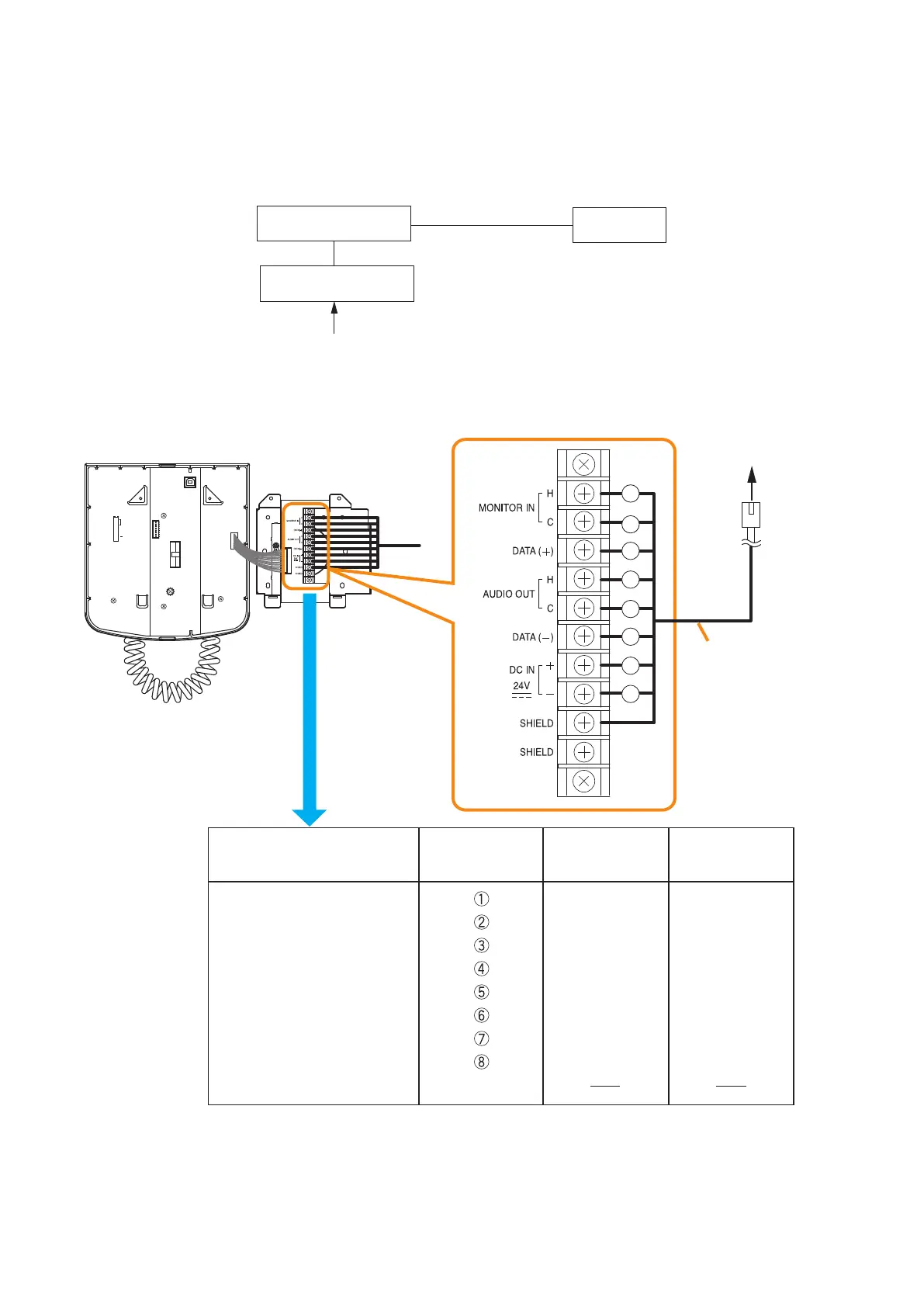
8.3.3. RM-200SF connection
Connect the RM-200SF to either of the RS LINK A or RS LINK B connector of the VX-3000F.
The maximum cable distance depends on how power is supplied.
[When power is supplied from the VX-3000F used with the VX-3000DS or the VX-3150DS]
8
7
6
5
4
3
2
1
TERMINATION
CPU OFF
LEVEL METER
COMMUNICATION
UNIT ID
OnOff
DIP SWITCH
MONITOR IN (H)
MONITOR IN (C)
DATA (+)
AUDIO OUT (H)
AUDIO OUT (C)
DATA (–)
DC IN 24 V (+)
DC IN 24 V (–)
SHIELD
Shield
Orange/White
Orange
Green/White
Blue
Blue/White
Green
Brown/White
Brown
Green/White
Green
Orange/White
Blue
Blue/White
Orange
Brown/White
Brown
Wall mount bracket unit
(supplied with the RM-200SF)
RJ45 connector
pin No.
Cable color
(T568B type)
Cable color
(T568A type)
RM-200SF rear
Wall mount bracket unit
(supplied with the RM-200SF)
Terminal block
To VX-3000F RS LINK A
or RS LINK B connector
Connection cable
(with RJ45 connectors)
1
2
3
4
5
6
7
8
VX-3000F
RM-200SF
VX-3000DS
or VX-3150DS
AC power
or
Battery