3-19
Chapter 3
INSTALLATION AND SETTING PROCEDURES (HARDWARE)
6. RM-200SF, RM-300X, AND RM-500 MICROPHONES
6.1. The ID Number Settings (RM-200F and RM-300X: Switches 1 – 3 operation or
RM-500: Switches 2 – 4 operation)
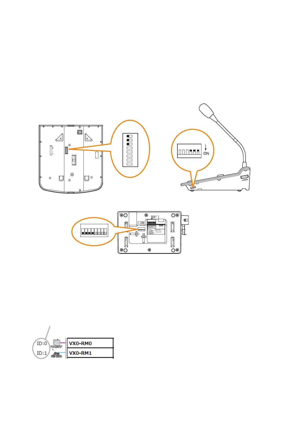
For the RM-200SF and the RM-300X, use Switches 1 to 3 of the DIP switch, and for the RM-500, use Switches
2 to 4* of the DIP switch to set the ID number (device number).
The DIP switch is located on the unit's rear panel for the RM-200SF, and on the side panel for the RM-300X,
and on the bottom panel for the RM-500.
* ID number setting switches of the RM-500 are assigned to Switches 1 through 4. Always, leave the Switch 1
"OFF" (factory default).
8
7
6
5
4
3
2
1
TERMINATION
CPU OFF
LEVEL METER
COMMUNICATION
UNIT ID
OnOff
DIP SWITCH
RM-200SF rear
RM-500 bottom
RM-300X side
1
2
ON
3
4
5
6
7
8
123456
1
ON
2 3 4 5 6 7 8
• A total of up to 8 RM-200SF, RM-300X, and RM-500 microphones can be connected per system.
If the system is required to comply with EN54-16, only a total of up to 2 RM-200SF and/or RM-300X units of
the 8 are allowed for connection. (See p. 3-59.)
• An ID Number must be set for each connected Remote microphone. The ID Number must be identical to
that which is set by the PC software. On the PC screen, the ID Number appears at the left of the Remote
microphone symbol.
[Remote microphone on the PC screen]
ID Number
• The ID Number is factory-preset to "0."