3-7
Chapter 3
INSTALLATION AND SETTING PROCEDURES (HARDWARE)
3. VX-300LO LINE OUTPUT MODULE
The VX-3000F is designed to accommodate the VX-300LO Line output modules by the number of the units
described below.
VX-3004F: Up to 4 units
VX-3008F: Up to 2 units
VX-3016F: Up to 2 units
[Line output module installation procedure]
Step 1. Shut off the power.
Shut off the power when the power is supplied to
the VX-3000F unit.
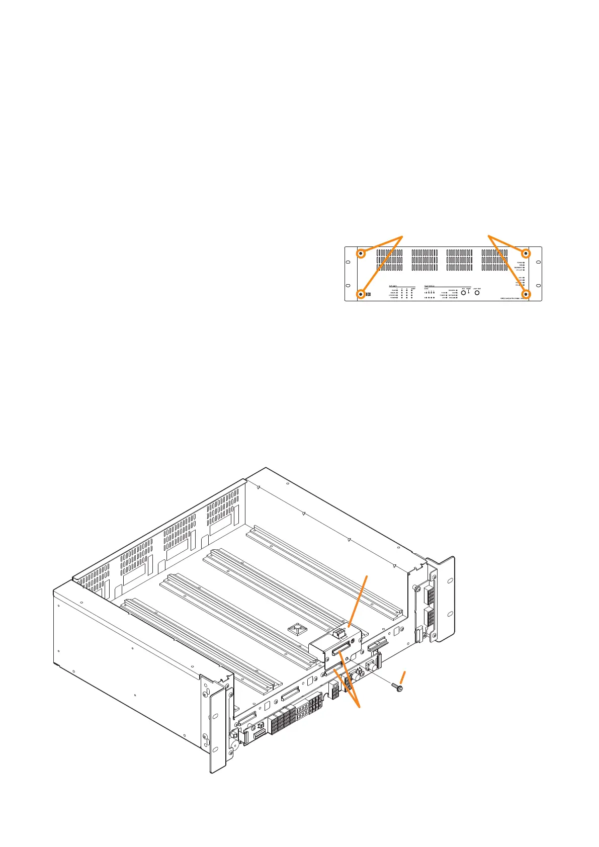
Step 2. Detach the front panel.
Remove 4 xing screws for front panel and detach
the front panel.
Step 3. Install the line output module.
Insert the line output module along the supporting runner, then secure it using a screw supplied with
the module.
Note
Use a #2 bit Philips screwdriver to tighten the xing screw.
Step 4. Make connection to the DA control link terminal.
Connect to the VX-3000F’s DA control link terminal using the cables supplied with the module.
Tip
If you cannot proceed with the procedure in the order from Steps 4 to 7 depending on the installation
situation, do it in the order that suits your convenience.
VX-3000F
Fixing screws for front panel
2
Machine screw with washer M4 x 8
(supplied with the VX-300LO)
DA control link terminal
VX-3000F
front
VX-300LO
4
3