3-81
Chapter 3
INSTALLATION AND SETTING PROCEDURES (HARDWARE)
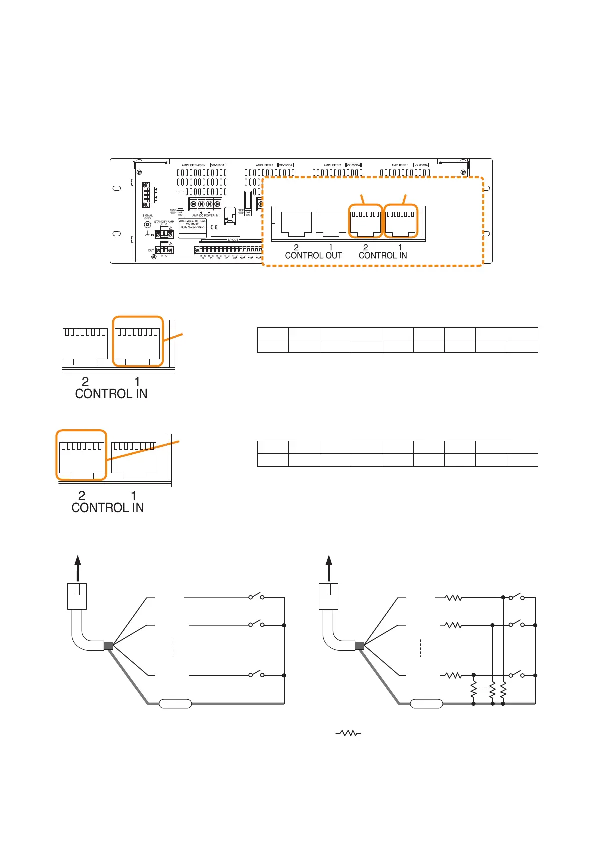
The RJ45's pin arrangement and pin functions are shown below.
[Control input terminal 1]
[Control input terminal 2]
8.6. Control Input Terminal Connections
The control input terminals are non-voltage contact inputs. Cable disconnection and short-circuit can be
detected using these input terminals.
Set the function, polarity, and failure detection using the VX-3000 Setting Software.
(See the separate Setting Software Instructions, "SURVEILLANCE SETTINGS," "Failure Pattern Settings,"
"Control Inputs Event Settings.")
87654321 87654321
VX-3000F
Control input terminal 2 Control input terminal 1
(Com)
RJ45 connector
pin No.
To VX-3000F
Shield
Cl_1
(Cl_9)
Cl_2
(Cl_10)
Cl_8
(Cl_16)
(Com)
RJ45 connector
pin No.
To VX-3000F
Shield
Cl_1
(Cl_9)
Cl_2
(Cl_10)
Cl_8
(Cl_16)
Connection when no failure detection is required Connection when failure detection is required
Note
When connecting the VM-300SV to detect failures such as cable disconnection, you need not connect any
resistors as they are connected inside the VM-300SV.
:
All resistor values are 4.7 kΩ. Connect
these resistors near the switch.
Pin1 Pin2 Pin3 Pin4 Pin5 Pin6 Pin7 Pin8 Shield
CI_1 CI_2 CI_3 CI_4 CI_5 CI_6 CI_7 CI_8 Com
Pin1 Pin2 Pin3 Pin4 Pin5 Pin6 Pin7 Pin8 Shield
CI_9 CI_10 CI _11 CI_12 CI_13 CI_14 CI_15 CI_16 Com
Control input
terminal 1
87654321 87654321
Control input
terminal 2
87654321 87654321