3-9
Chapter 3
INSTALLATION AND SETTING PROCEDURES (HARDWARE)
Step 1. Detach the front panel.
Remove 4 xing screws for front panel and detach
the front panel.
Notes
• When setting the ID number for multiple VX-3000F units, assign different numbers to each unit. The ID
number that can be used must not exceed the actual number of VX-3000F units set using the VX-3000
Setting Software.
• If an ID number is duplicated, then the VX-3000F units assigned that number cannot be controlled by the VX-
3000F system.
• The VX-3000F set to ID "0" plays a role of a leader in the whole system, displaying the "GENERAL FAULT"
indication and outputting its signal when malfunction occurs within the system.
• In a single VX-3000F conguration, set the ID number to "0."
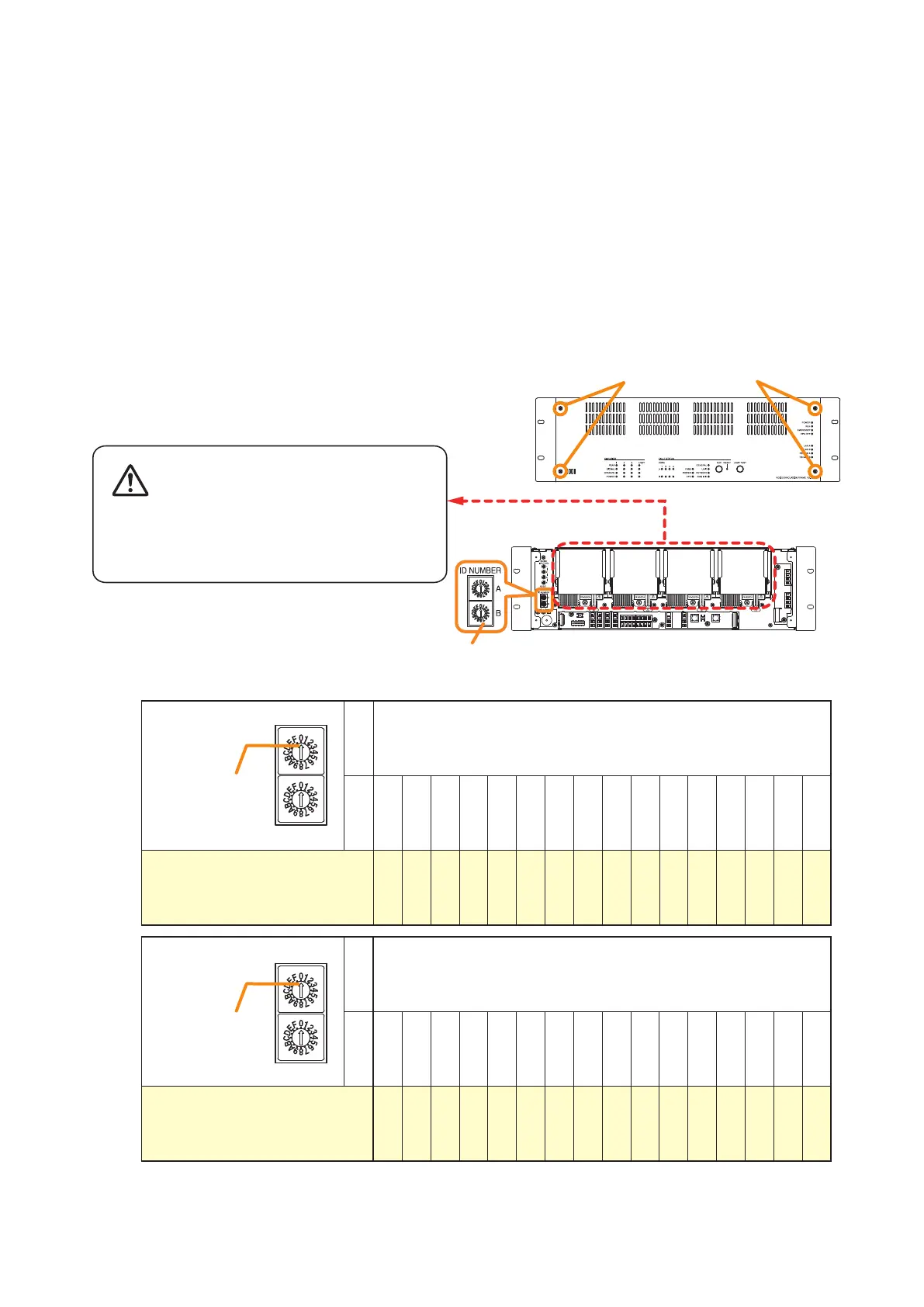
[ID number setting]
Note: The ID number is set to No. 0 by default.
ID switch
A 0
B 0 1 2 3 4 5 6 7 8 9 A B C D E F
ID number 0 1 2 3 4 5 6 7 8 9 10 11 12 13 14 15
Arrowhead
ID NUMBER
A
B
ID switch
A 1
B 0 1 2 3 4 5 6 7 8 9 A B C D E F
ID number 16 17 18 19 20 21 22 23 24 25 26 27 28 29 30 31
Arrowhead
ID NUMBER
A
B
VX-3000F front
Fixing screws for front panel
1
2
ID Switch
VX-3000F front
(Front panel detached)
There is a high voltage section inside the power
amplifier's filter. Never insert your finger or
metallic objects inside the unit.
Step 3. Replace the front panel.
Secure it using 4 xing screws for front panel .
3.1. The ID Number Setting
Step 2. Set the ID switches.