3-65
Chapter 3
INSTALLATION AND SETTING PROCEDURES (HARDWARE)
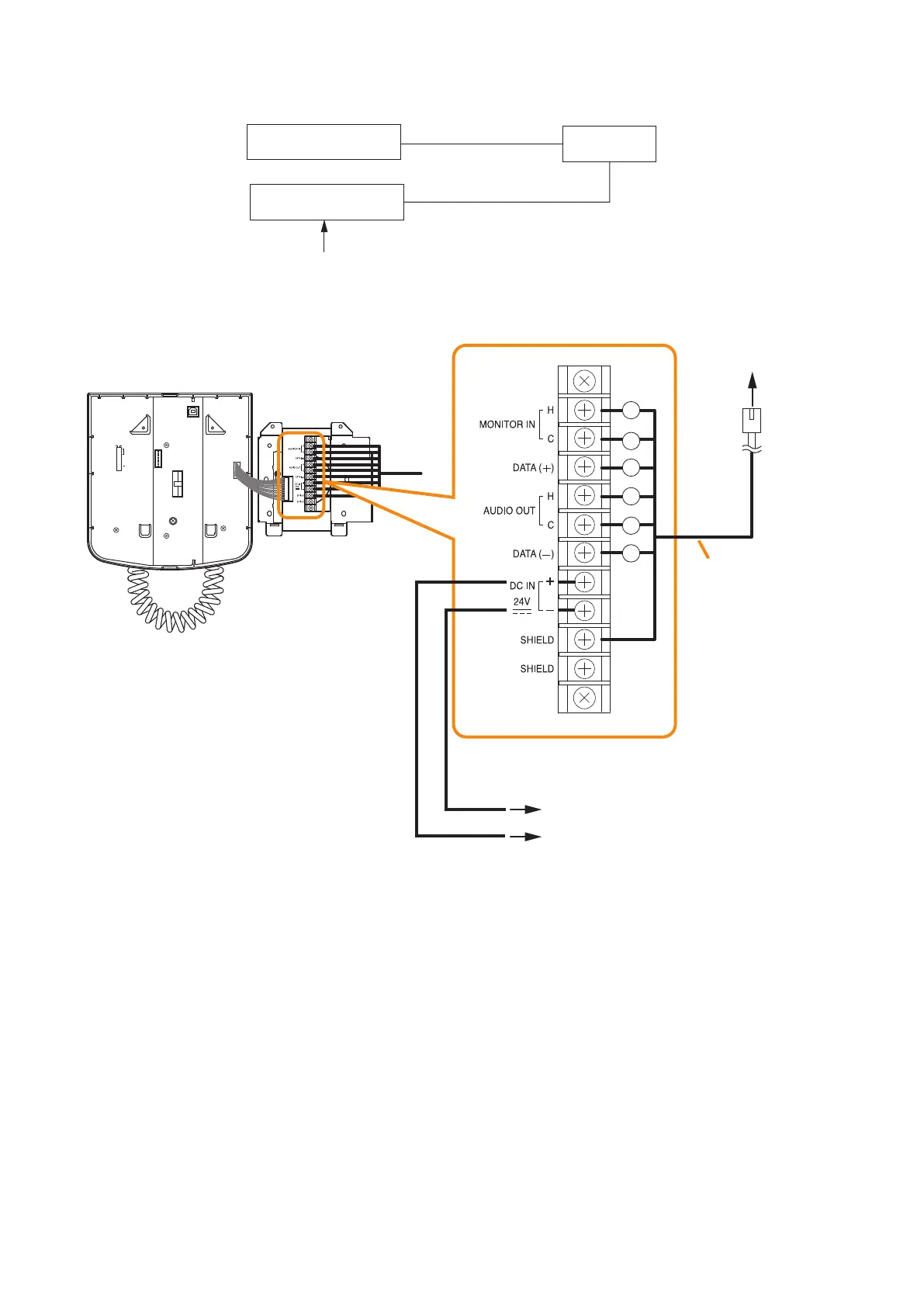
[When power is supplied from the VX-3000DS or the VX-3150DS]
8
7
6
5
4
3
2
1
TERMINATION
CPU OFF
LEVEL METER
COMMUNICATION
UNIT ID
OnOff
DIP SWITCH
RM-200SF rear
Wall mount bracket unit
(supplied with the RM-200SF)
1
2
3
4
5
6
VX-3000DS’ or VX-3150DS’
DC POWER OUT terminal
(–)
(+)
Connection cable
(with RJ45 connectors)
To VX-3000F RS LINK A
or RS LINK B connector
Terminal block
VX-3000F
RM-200SF
VX-3000DS
or VX-3150DS
AC power
or
When a STP Category 5 straight cable is used as communication cable (excluding power line) between the
RM-200SF and the VX-3000F, the maximum cable distance in a system is 1200 m in total.