2-17
Chapter 2
NOMENCLATURE AND FUNCTIONS
11. Volume control knobs
Adjusts the volume level of theVX-3000F's audio
input or audio output in the range of –∞ to 0 dB.
The volume decreases as the knob is rotated
clockwise, and increases as the knob is rotated
counterclockwise.
Which volume level of the input channel or the
output zone is to be adjusted can be assigned
to the volume control using the VX-3000 Setting
Software.
(See the separate Setting Software Instructions,
"VX-3000CT Setting.")
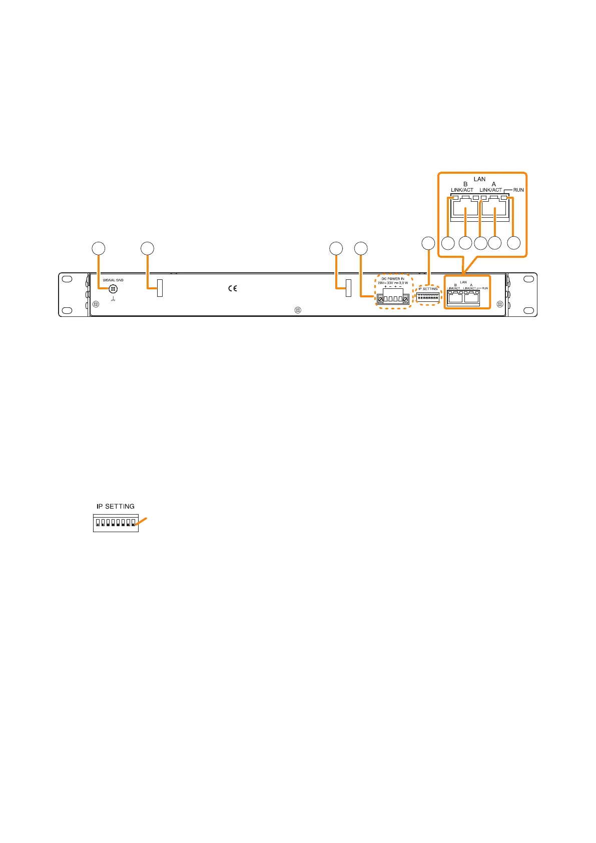
[Rear]
12 13 13 14
15 1616
17 17 18
12. Signal ground terminal
Be sure to ground this terminal for surge protection.
Note: This terminal is not for protective ground.
13. Cord clamps
Secures the power cord. (See p. 3-95.)
14. DC Power input terminals
Power is supplied to this terminal from the VX-
3000DS or VX-3150DS Power supply manager or
the AD-246 AC Adapter.
15. IP address setting switch
Sets the unit's IP address.
(Factory default setting: All set to OFF)
• Switch 1
Sets whether to enable or disable IP address
setting by the IP address setting switch.
ON: Enables the IP address set by the IP
address setting switch.
OFF: Disables the IP address set by the IP
address setting switch and enables
the one set using the VX-3000 Setting
Software.
• Switches 2 – 8
Set the IP address by ON/OFF combination of 7
switches. (See p. 3-14.)
Notes
• If you have reset the IP address after power-on,
be sure to restart the unit.
• The IP address setting switch allows the
IP address to be set only in the range of
"192.168.14.111" to "192.168.14.200". If you
wish to set IP address out of this range, set it
using the VX-3000 Setting Software. (See the
separate Setting Software Instructions, "UNIT
DETECTION AND NETWORK SETTINGS.")
16. LINK/ACT indicators
Indicates the connection status of the LAN
connection terminal.
Lights or ashes when the connection is correct.
Remains unlit when no connection is established.
17. LAN link connectors
Connect the VX-3000 system components or
switching hubs. (See p. 3-83 "VX-3000 Unit's
LAN Link Connector Connection.")
18. RUN ind icator
Continuously ashes when the unit's CPU is
operating normally.
OFF
ON
OFF side
Note: Switches 1 through 8 numbered from left to right.