3-4
Chapter 3
INSTALLATION AND SETTING PROCEDURES (HARDWARE)
Step 1. Shut off the power.
Shut off the power when the power is supplied to
the VX-3000F unit.
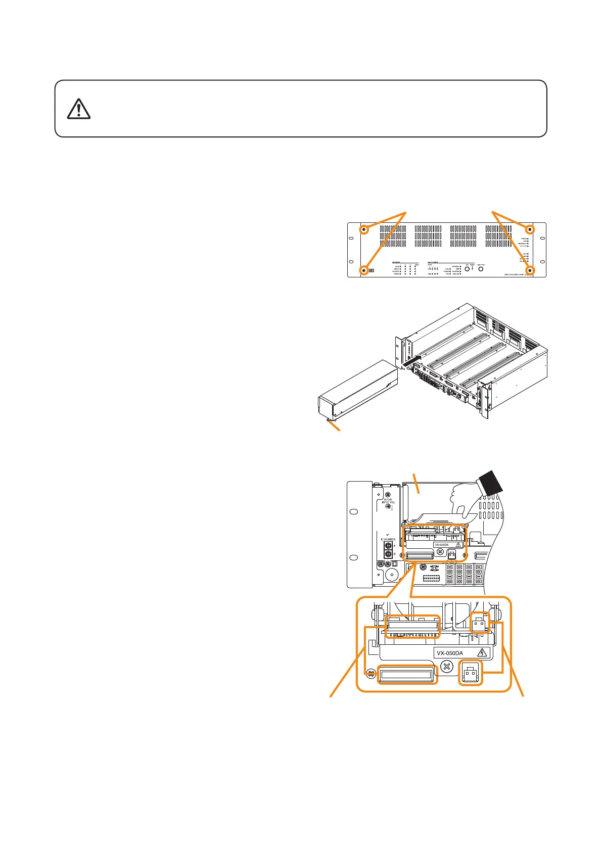
Step 2. Detach the front panel.
Remove 4 xing screws for front panel and detach
the front panel.
Step 3. Install the digital power amplier module.
Insert the power amplier module along the
supporting runner until it will not go any further, then
secure it using a power amplier module xing screw.
Note
Use a #2 bit Philips screwdriver to tighten the xing
screw.
Step 4. Lift the lower portion of the lter, then connect
cables.
4-1. Connect both the power amplier module's DA
control link connector and DA output link connector
to the VX-3000F's corresponding connectors.
Use the cables supplied with the power amplier
module.
Note
After the cable connection is complete, be sure
to push the cables against the amplier side to
prevent them from protruding so that the front panel
can be easily mounted without obstructing its work.
4-2. Replace the lter.
Step 5. When installing two or more power amplier
modules, repeat Steps 3 and 4.
Step 6. Replace the front panel.
Secure it using 4 xing screws for front panel.
VX-3000F
Fixing screws for front panel
2
3
VX-3000F
front
VX-015DA/
030DA/050DA
[Power amplifier installation procedure]
There is a high voltage section inside the power amplier's lter. Never
insert your nger or metallic objects inside the unit. When attaching or
detaching the connector, never touch the internal components other
than connectors.
WARNING
4
DA control link connector DA output link connector
Filter