Verifying Aux Antenna to Boom Length
P/N 7010-0697
4-11
• If the Extended position is larger, rotate (decrease) the machine
position in 3DMC center-wise.
• If the Curled In position is
larger, rotate (increase) the
machine position in 3DMC
outwards.
To rotate the machine’s position
center-wise, decrease the Aux
antenna distance-to-boom center value in 3DMC using the following
steps. Do not physically move the antenna.
1. Divide the Delta error by 2.
2. Roughly measure the distance from the Main antenna to the
extended bucket teeth (e.g. 30 Ft.).
3. Note the distance between antennas (e.g. 7.5 Ft.).
4. Divide the Main antenna-to-bucket teeth distance by the distance
between antennas.
5. Divide the Delta error by this number.
6. In 3DMC, navigate to the Excavator Antenna Mounting screen in
the machine builder. Reduce the Aux antenna-to-boom pivot by
0.03 Ft.
Table 4-2. Error in Length Measurement
Curled In Extended
Facing N 520.39 520.27
Facing S 520.38 520.51
Delta 0.24
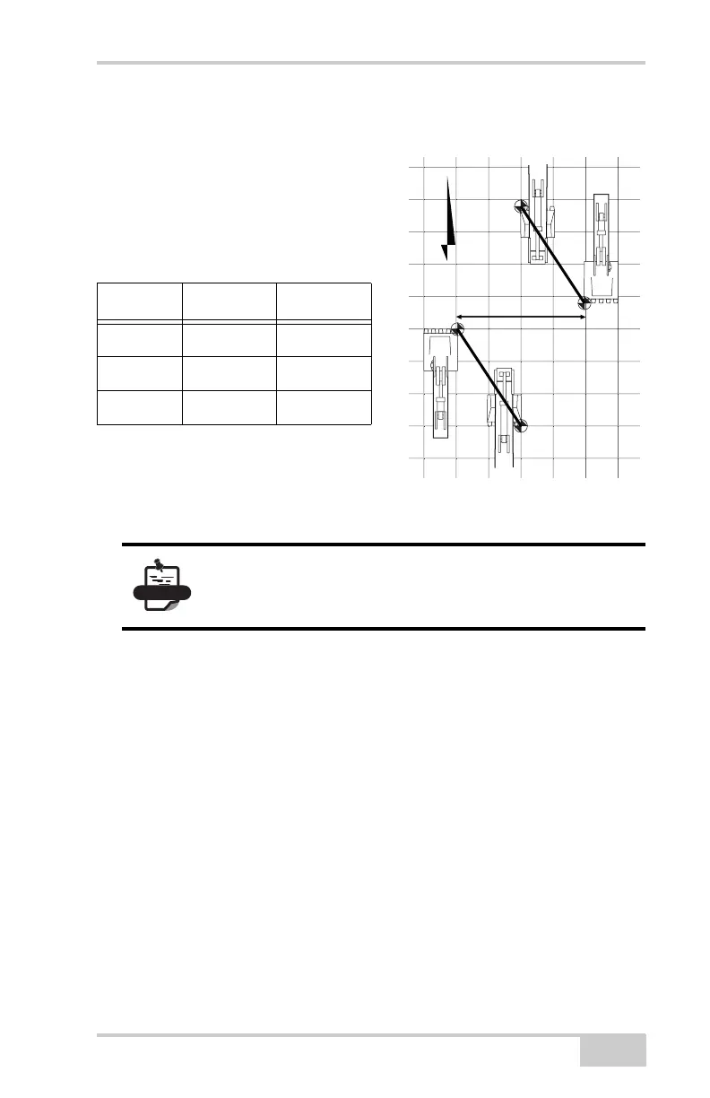
If the lines are offset but equal in distance, the
rotation is correct. Continue with “Verifying the
Main Antenna” on page 4-12.
N
Extended
0.24
Curled In
Extended
Curled In