Verifying Aux Antenna to Boom Length
P/N 7010-0697
4-7
Verifying Aux Antenna to Boom
Length
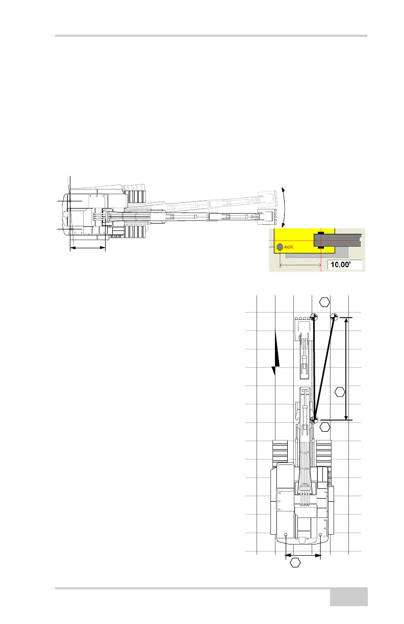
The position of the Main antenna to the Aux antenna determines GPS
heading. The distance from the Aux antenna to the boom pivot
determines the rotational heading of the machine. Small errors in this
measurement may have a significant rotational position error at the
bucket.
Figure 4-7. Aux Antenna-to-Boom Pivot
Method A: Using a Survey Rover
1. Create a flat plane design file.
2. Position the machine directly North
(both edges of the bucket will have
the same Northing value).
3. Curl the bucket in and record the
Easting value of a bucket corner
with the Rover (e.g. 520.38).
4. Record the 3DMC Easting value
for the same corner (e.g. 520.35).
5. Extend the bucket to its fullest
extent and record the Rover
Easting value (e.g. 520.51).
6. Record the 3DMC Easting value
for the same corner (e.g. 520.36).
• The difference in curled
positions is
N
3DMC
0.15Ft
7.5Ft
A
Survey Rover
D
B
C
20Ft
0.03Ft
Two Machine Positions over Two Points