Verifying X63/X62 Setup
X63/X62 Installation and Calibration Manual
4-12
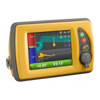
7. Repeat steps 1 to 13 page 4-10 to verify the correction. There
should be no difference between the North and South numbers.
Figure 4-9. “Rotate” Aux Antenna on Body
Verifying the Main Antenna
This process is similar to checking the rotational error in the Aux
position, but will appear as a constant offset when comparing the
curled vs. extended values.
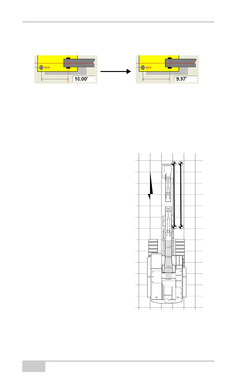
Method A: Using a Survey Rover
1. Create a flat plane design file.
2. Position the machine directly North
(both edges of the bucket will have
the same Northing value).
3. Curl the bucket in and record the
Easting value of a bucket corner
with the Rover (e.g. 520.38).
4. Record the 3DMC Easting value
for the same corner (e.g. 520.35).
5. Extend the bucket to its fullest
extent and record the Rover
Easting value (e.g. 520.51).
6. Record the 3DMC Easting value
for the same corner (e.g. 520.48).
• The difference in curled
positions is
• The difference in extended positions is
7. Plot the Easting lines to show the offset error between Rover and
3DMC is constant when curled or extended.
Step 3-4:
bucket
curled in
Step 5-6:
bucket
extende