Rev. 000
HYDRAULIC LIFT ASSEMBLY
7-18
TX 413 Service Manual
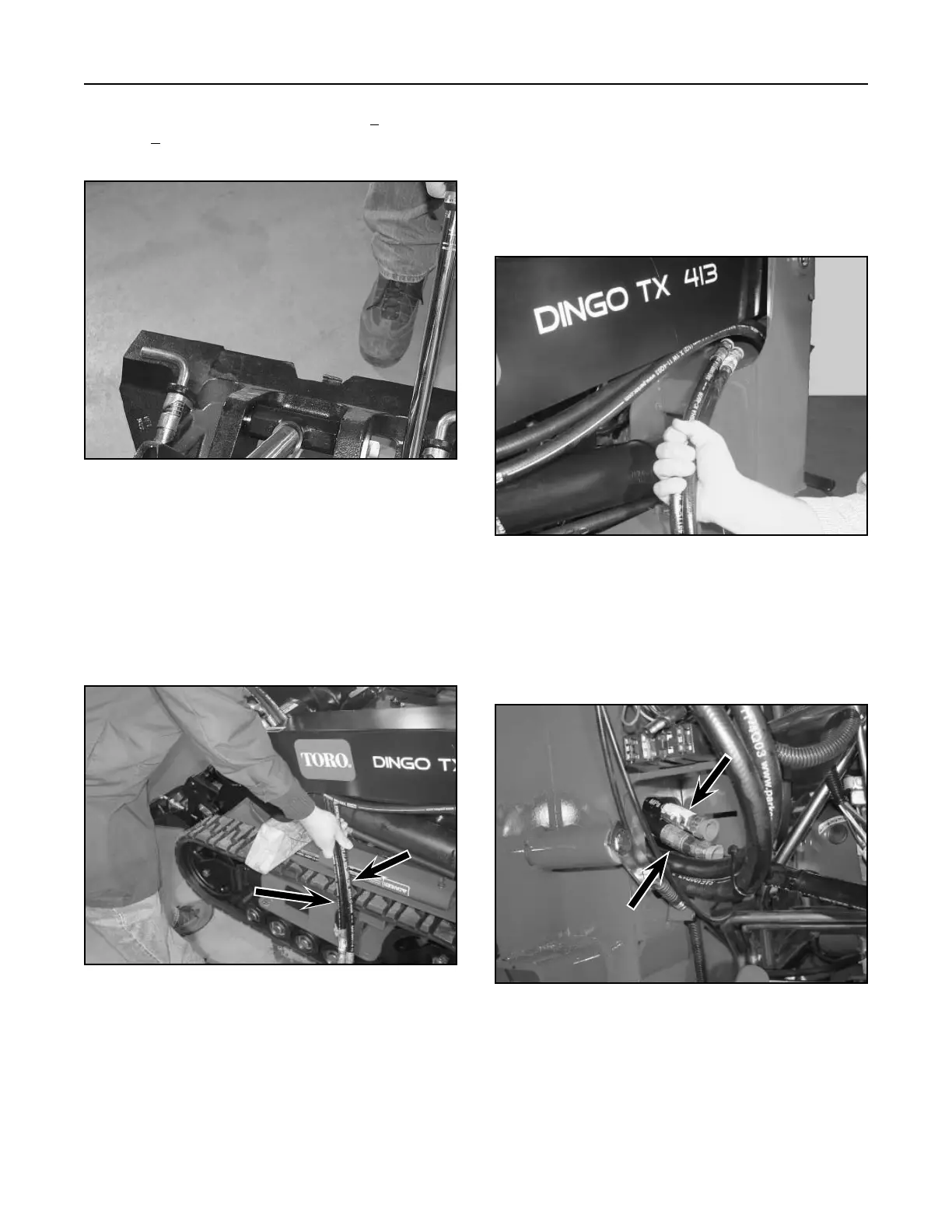
9. The hydraulic hoses are then pulled through the
back of the frame. Make sure the hose (Fig. 249,
Ref. D) is on top of the hydraulic hose (Fig 249,
Ref. C).
Figure 249 DSC-0994
6. Route the two hydraulic hoses from the tilt
cylinder into the front opening of the loader arm,
behind the auxiliary quick couplers. Make sure
the hydraulic hose (Fig. 247, Ref. D) is routed
to the outside (Fig. 247, Ref. C) of the hydraulic
hose. Both hydraulic hoses should be routed to
the inside of the auxiliary hoses.
Figure 247 DSC-0992
7. Feed the hydraulic hoses toward the back of the
loader arm. Make sure the hoses are routed to
the inside of the auxiliary hoses that go to the
quick couplers.
8. Route the two hydraulic hoses up from the tilt
cylinder through the upper frame hole (Fig. 248).
Figure 248 DSC-0993
D
C
5. Install shoulder bolt and torque to 16 + 2 ft-lbs.
(21.7 + 2.7 Nm) (Fig. 246). Apply grease to the
grease fitting with a grease gun.
Figure 246 DSC-0990
D
C