Rev. 000
TX 413 Service Manual
7-19
HYDRAULIC LIFT ASSEMBLY
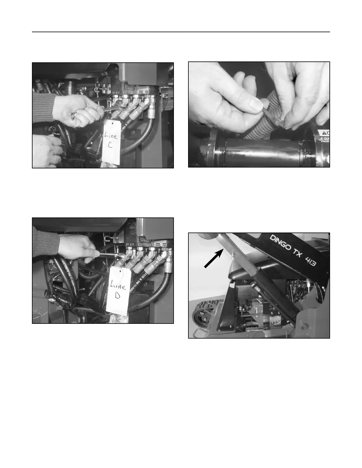
11. Connect the hydraulic hose, Ref. D, to the
hydraulic lift valve fitting and tighten (Fig. 251).
Figure 251 DSC-0970
10. Connect hydraulic hose (Fig. 250, Ref. C) to the
hydraulic lift valve fitting and tighten.
12. Using a cable tie, tie the two hydraulic tilt hoses,
3" (7.62cm) from the barrel end fitting (Fig. 252).
Figure 250 DSC-0971
Figure 252 DSC-0995
13. Start the unit and raise the loader arm assembly
to the full raised position. Install the cylinder lock
assembly on the hydraulic lift cylinder. Shut the
engine off (Fig. 253).
Figure 253 DSC-0965
A
A. Cylinder lock