Rev. 000
TX 413 Service Manual
7-29
HYDRAULIC LIFT ASSEMBLY
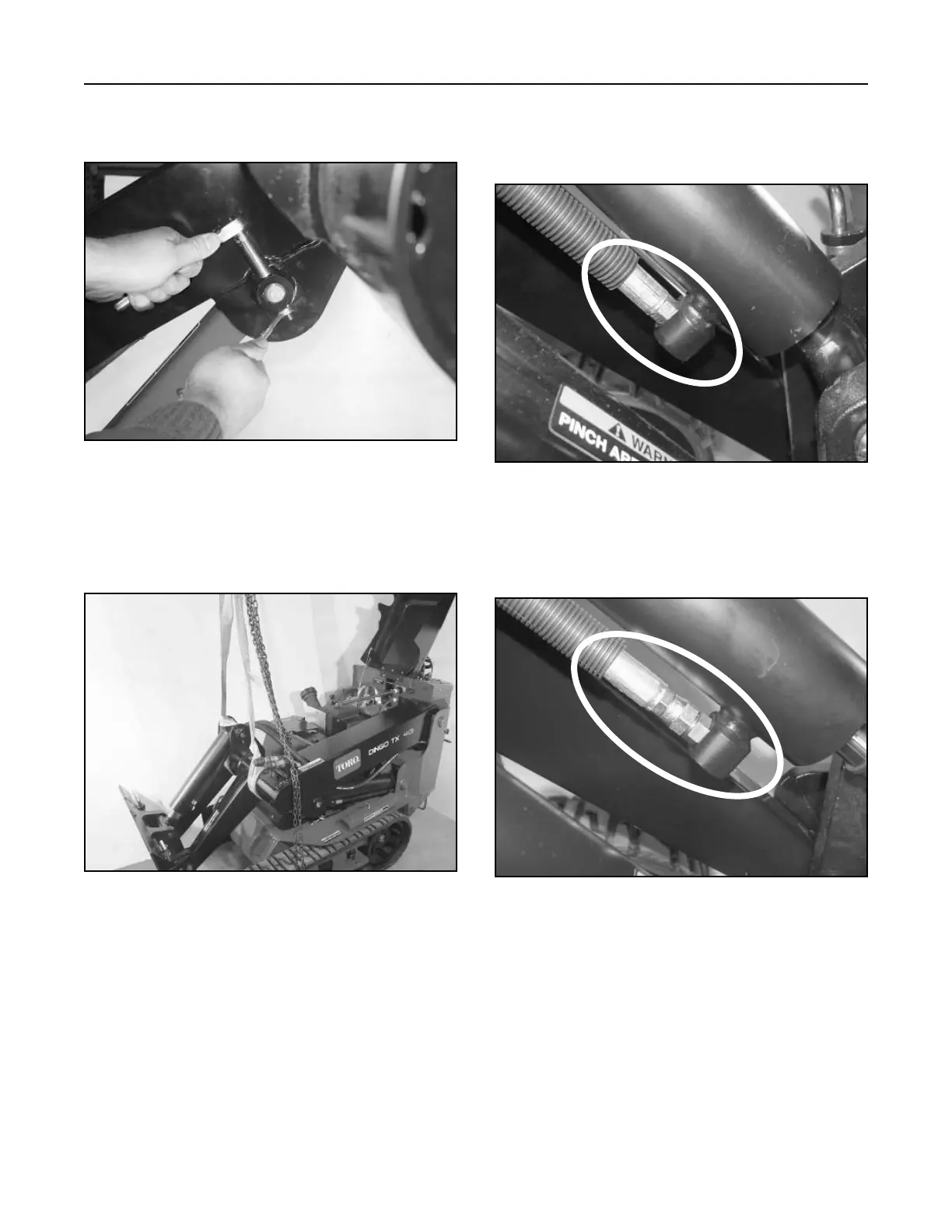
4. Remove the bolt and nut retaining the pivot pin
on the ram end of the lift cylinder (Fig. 288).
Figure 288 DSC-1043
5. Remove the cylinder lock and lower lift arm.
Support the loader arm assembly with an
overhead lift (Fig. 289).
Figure 289 DSC-1069
Note: Units with serial numbers from 240000100
through 240000200 have a fixed fitting
(Fig. 290).
Figure 290 DSC-1029
Note: Units with serial numbers from 240000201
and higher have a swivel fitting (Fig. 291).
Figure 291 DSC-1030