Rev. 000
HYDRAULIC LIFT ASSEMBLY
7-30
TX 413 Service Manual
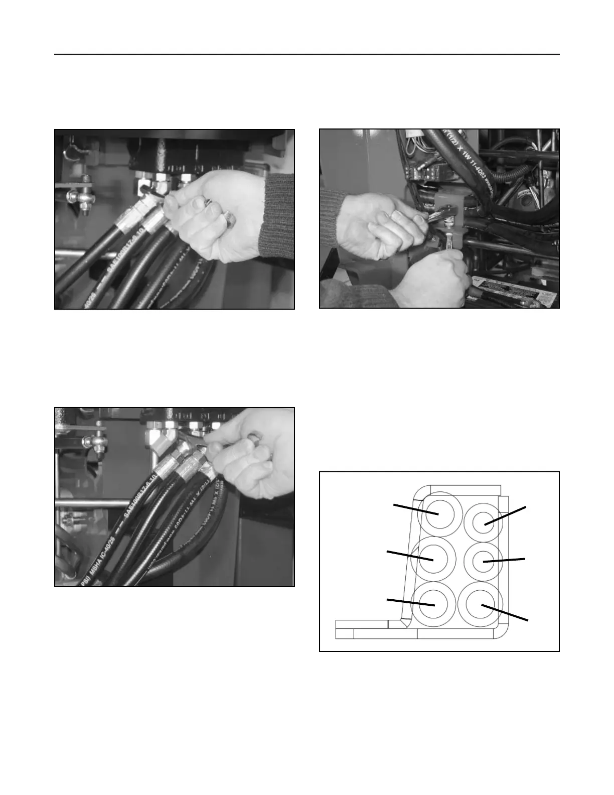
Proper hose placement through the clamp (Fig.
295).
A. Auxiliary Hose (female coupler)
B. Auxiliary Hose (male coupler)
C. Lift Cylinder Hose (ram end)
D. Tilt Cylinder Hose (ram end)
E. Tilt Cylinder Hose (barrel end)
F. Lift Cylinder Hose (barrel end)
Figure 295 105-9000 clamp
Front
Rear
A
B
C
D
E
F
8. Cut the cable ties around the hydraulic hoses.
Remove the hydraulic hose clamp located in the
back at the lower left corner and cut the cable tie
holding the two hoses together (Fig. 294).
Figure 294 DSC-0969
6. At the loader arm valve, mark the tilt cylinder
hydraulic hose and fitting with paint or marker.
Remove the hydraulic hose from the fitting (Fig.
292).
Figure 292 DSC-1045
7. Remove the hydraulic hose that goes to the tilt
hydraulic cylinder and remove from the fitting at
the hydraulic loader valve (Fig 293).
Figure 293 DSC-1047