Rev. 000
TX 413 Service Manual
7-43
HYDRAULIC LIFT ASSEMBLY
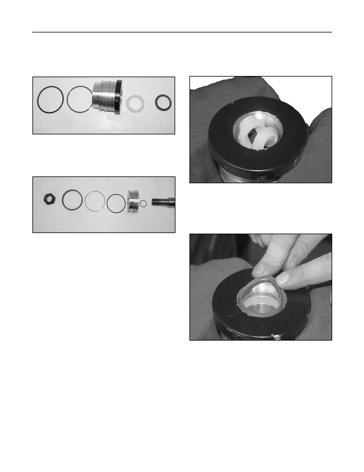
3. Install one edge of the wiper seal and work it
around inner lip in the head (Fig. 340).
Figure 340 DSC-1352
2. Lubricate the head and all seals with 10W-30 oil
prior to installation. Using round-nose pliers, twist
the dual lip u-cup seal into a "C" shape and allow
it to snap into the groove (Fig. 339).
Figure 339 DSC-1351
1. Visually inspect for material defects and
contamination. All seals and O-rings must be
replaced with new parts (Head Assembly, Fig.
337, and Piston Assembly, Fig. 338).
Figure 337 DSC-1348
Figure 338 DSC-1350
A. Wiper D. Static Back-up
B. U-Cup E. Static O-Ring
C. Head
A. Locknut E. Bi-directional Piston
B. PRS Static O-ring Seal
C. Piston F. Wear Ring
D. O-ring Loader G. Rod
AB
CD
E
A
B
CDE
FG