Rev. 000
HYDRAULIC LIFT ASSEMBLY
7-44
TX 413 Service Manual
Figure 343 DSC-1359
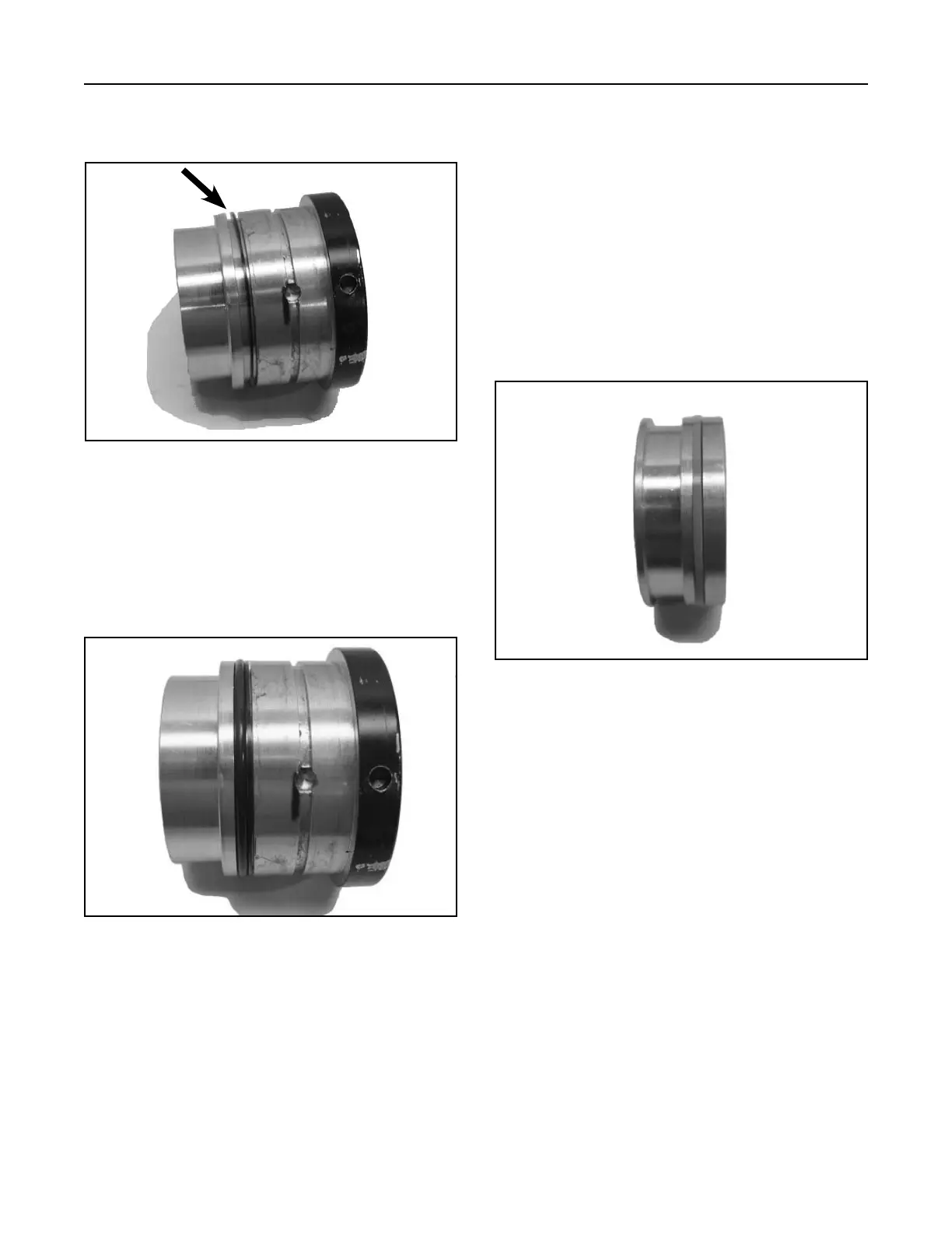
5. Next, install the O-ring around the groove, next to
the Static Back-up Ring (Fig. 342).
Note: If possible, the head/seal assembly should
sit for at least one hour to allow the seals
to normalize.
Figure 342 DSC-1356
6. For easiest installation, warm Bi-directional
Piston Seal (Teflon seal) in 120° to 150° F (48.9°
to 65.6°C) 10W-30 oil. Lubricate the piston and
all components with oil. Stretch the 0-ring Loader
Seal into the groove in the piston.
7. Verify that the o-ring is not pinched or twisted.
8. Remove the bi-directional piston seal from the
warm fluid and install it around the end of the
piston, then push it into the piston groove over
the o-ring loader seal (Fig. 343).
Be careful not to cut the OD of this seal.
4. Install the Static Back-Up ring around the groove
in the head (Fig. 341).
Figure 341 DSC-1355