ATTACHMENTS
10-28 TX 413 Service Manual
Rev. 001
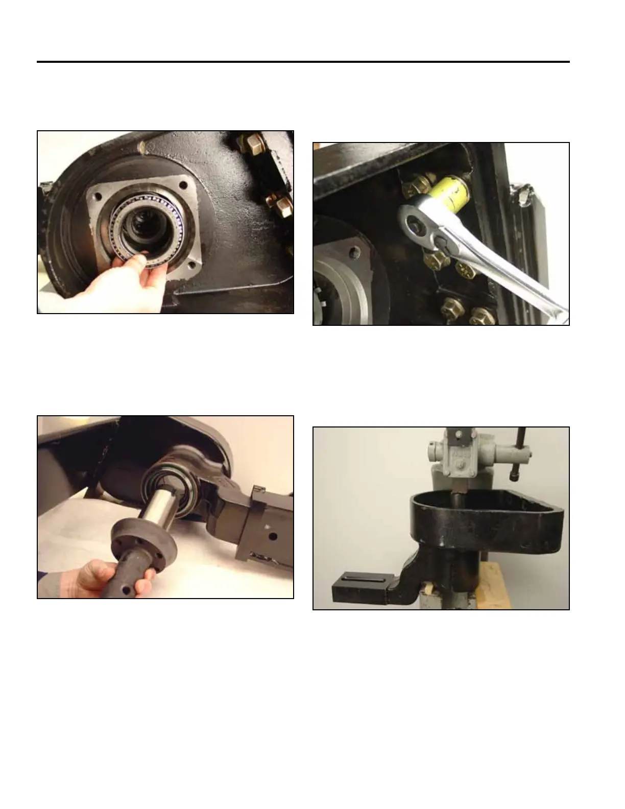
Fig 100 CLR DSC-0303
6. Remove the roller bearing from the trencher shaft
(Fig. 100).
Fig 101 CLR DSC-0305
7. From the sprocket side of the trencher boom mount,
remove the trencher shaft (Fig. 101).
Fig 103 CLR DSC-0310
9. Block the boom mount on a press so the spacer and
shaft seal will press out freely (Fig. 103).
Fig 102 CLR DSC-0353
8. If the motor side bearing needs replacement pro-
ceed as follows. Remove boom mount from mount
assembly (Fig. 102).