ATTACHMENTS
10-31TX 413 Service Manual
Rev. 001
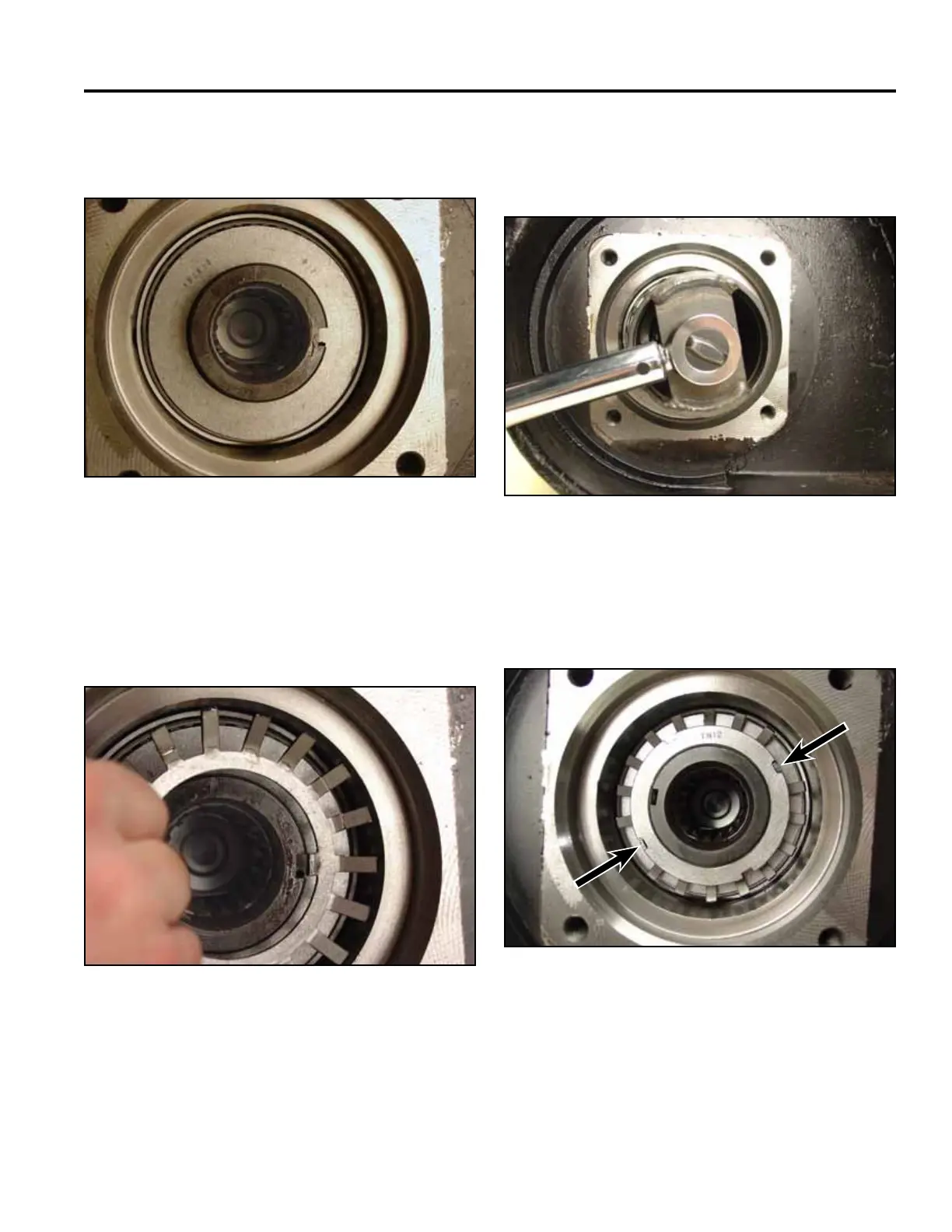
Fig 112 CLR DSC-0347
7. Line up the tab on the tongued washer with the
trencher shaft keyway and install (Fig. 112).
8. Line up the inner tab of the bearing lockwasher with
the trencher shaft keyway and install (Fig. 113).
Note: The angle of the bearing lockwasher tabs
should face up.
Fig 113 CLR DSC-0348
9. Use a large slotted screwdriver to prevent the
trencher shaft from spinning and install the bearing
locknut.Torqueto45ft-lbs.(61Nm)(Fig.114).
Fig 114 CLR DSC-0351
Fig 115 DSC-352
10. Afterthepropertorquevaluehasbeenreached,line
up two of the lockwasher tangs and bend into the
slots on the locknut (Fig. 115).