ATTACHMENTS
10-32 TX 413 Service Manual
Rev. 001
Fig 116 CLR DSC-0355
11. Rotate the shaft to ensure the bearings are properly
seated.
12. Boltthemountassemblytotheboomandtorquethe
six screws to 210 + 20 ft-lbs. (285 + 28 Nm) (Fig.
116).
Note: The three inside screws are difcult to torque
with a standard prole socket and torque
wrench combination. Torque the outer three
screws and ensure the inside screws are
securely tightened.
Note: Install sprocket before hydraulic motor.
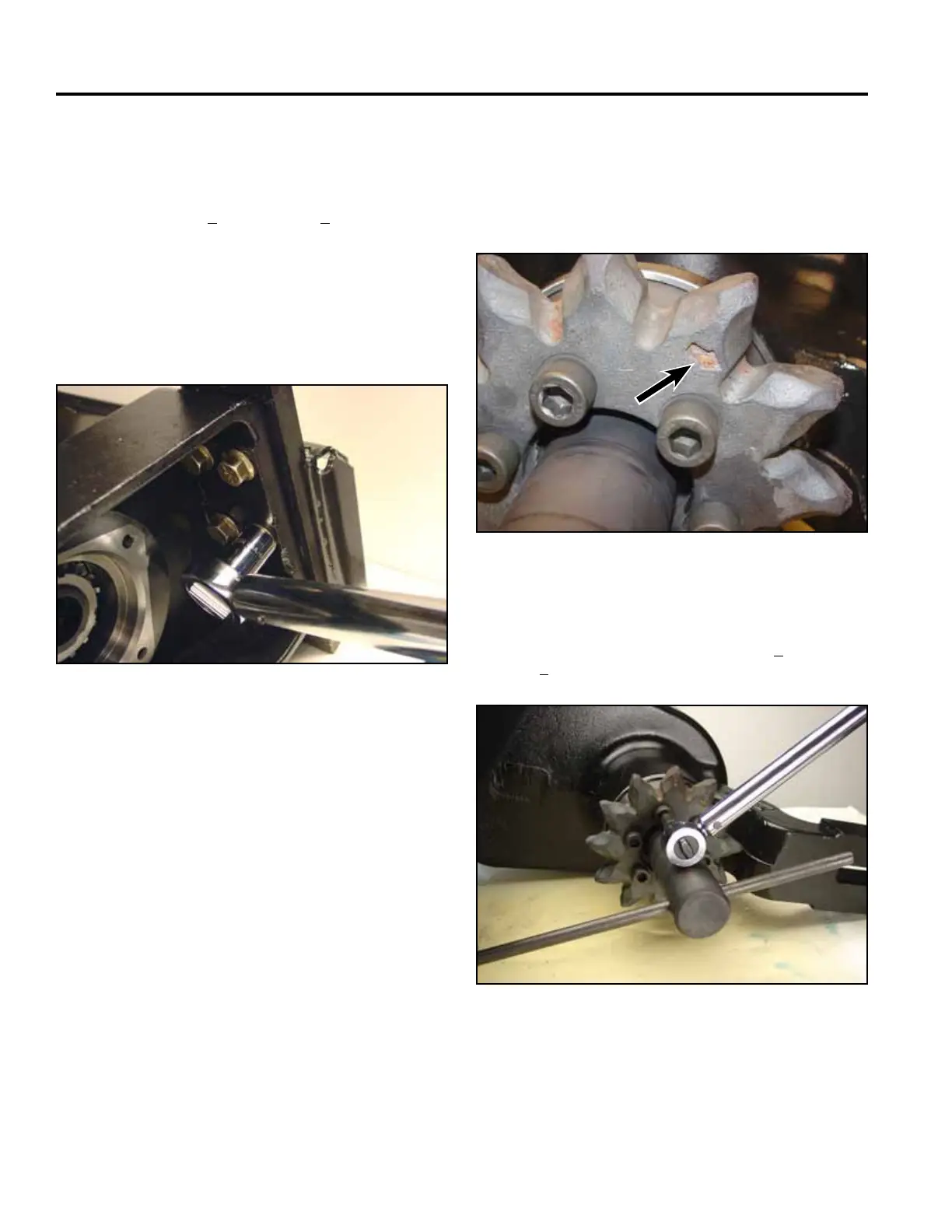
13. The sprocket is installed with the recessed side
facing the trencher arm. The arrow side faces out
toward the spoils auger (Fig. 117).
Fig 117 CLR DSC-0359
14. Secure the trencher drive shaft so it will not rotate.
Torquethesixhexheadscrewsto105+ 11 ft-lbs.
(142 + 15 Nm) (Fig. 118).
Fig 118 CLR DSC-0360