ATTACHMENTS
10-33TX 413 Service Manual
Rev. 001
Fig 120 CLR DSC-0357
16. Install the hydraulic motor onto the boom mount
withtheportsfacingup.Torquethefourscrewsto
75 + 8 ft-lbs. (102 + 11 Nm) (Fig. 120).
Fig 119 CLR DSC-0362
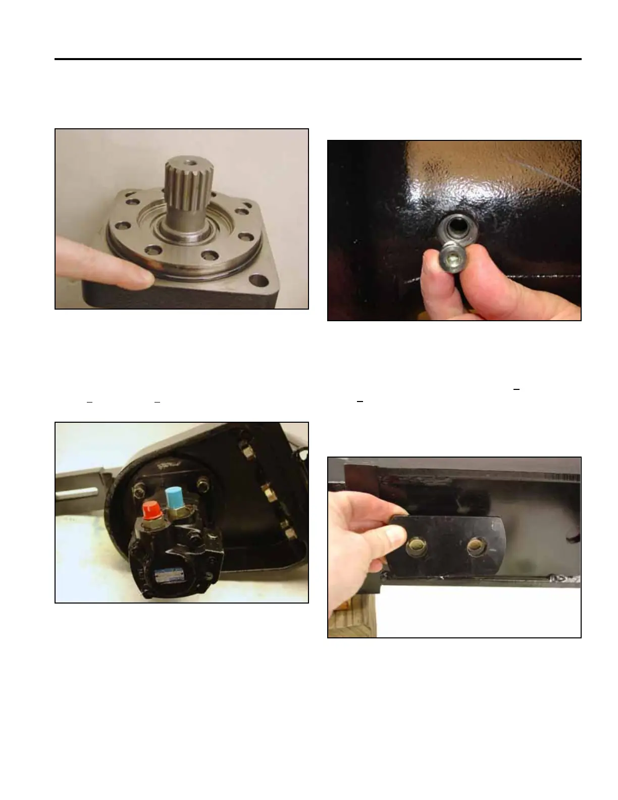
15. Install new o-ring onto the hydraulic motor prior to
mating it with the trencher shaft (Fig. 119).
17. Level the trencher arm before servicing the bearing
reservoir.Removethellplug.Fillwith16oz.of
SAE 90 - 140 AP 1 Service GL-4 or GL5 (Fig. 121).
Fig 121 CLR DSC-0364
18. Reinstallthellplugandtorqueto11+ 2 inch-lbs.
(1 + .23 Nm).
19. Install boom onto trencher arm. Place the plate
supports on either side of the boom (Fig. 122).
Fig 122 CLR DSC-0367