g028240
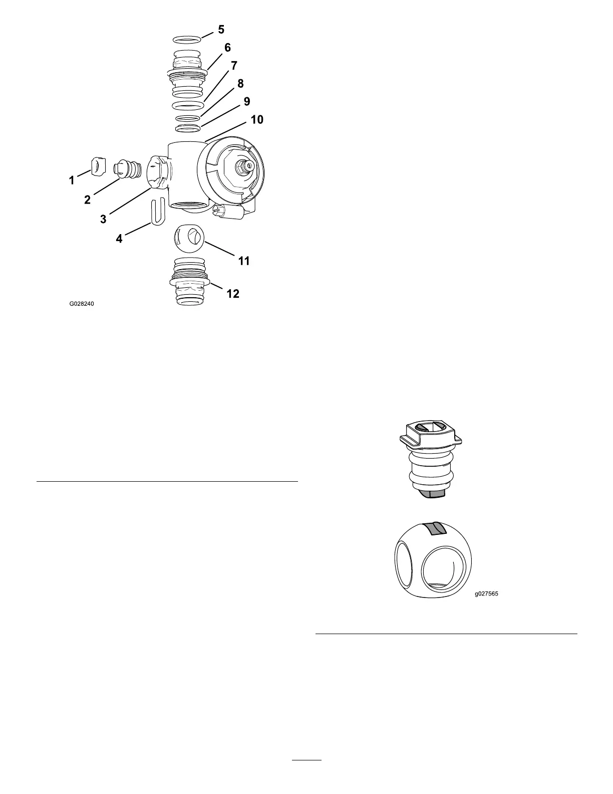
Figure73
SectionValveManifold
1.Valve-stemseat
7.End-capO-ring(0.796x
0.139inch)
2.Valve-stemassembly
8.BackseatingO-ring(0.676
x0.07inch)
3.Stemport
9.Ballseat
4.Stemretainer10.Manifoldbody
5.OutletttingO-ring(0.737
x0.103inch)
11.Ballvalve
6.Coupling(manifold)12.Couplingassembly
(manifold)
3.Turnthevalvestemsothattheballisinthe
openposition(Figure71A).
Note:Whenthevalvestemisparallelwiththe
valveow,theballslidesout.
4.Removethestemretainerfromtheslotsinthe
stemportinthemanifold(Figure72andFigure
73).
5.Removethestemretainerandvalvestemseat
fromthemanifold(Figure72andFigure73).
6.Reachintothemanifoldbodyandremovethe
valve-stemassembly(Figure72andFigure73).
7.Cleantheinsideofthemanifoldandexterior
oftheballvalve,valve-stemassembly,stem
capture,andendttings.
AssemblingtheManifoldValve
1.Checktheconditionoftheoutlet-ttingO-rings
(section-valvemanifoldonly),end-capO-rings,
backseatingO-rings,ballseatfordamageor
wear(Figure72andFigure73).
Note:ReplaceanydamagedorwornO-rings
orseats.
2.Applygreasetothevalvestemandinsertitinto
thevalve-stemseat(Figure72andFigure73).
3.Installthevalvestemandseatintothemanifold
andsecurethestemandseatwiththestem
retainer(Figure72andFigure73).
4.EnsurethatthebackseatingO-ringandtheball
seatarealignedandseatedintotheend-cap
tting(Figure72andFigure73).
5.Installtheend-cap-ttingassemblyontothe
manifoldbodyuntiltheangeoftheend-cap
ttingtouchesthemanifoldbody(Figure72
andFigure73),thenturntheend-capttingan
additional1/8to1/4turn;torquethettingto225
to282N∙cm(20to25in-lb).
Note:Usecautionsoasnottodamagetheend
ofthetting.
6.Inserttheballintothevalvebody(Figure74).
Note:Thevalvestemshouldtinsidetheball
driveslot.Ifthevalvestemdoesnott,adjust
thepositionoftheball(Figure74).
g027565
Figure74
7.Turnthevalve-stemassemblysothatthevalve
isclosed(Figure71B)
8.Repeatsteps4and5fortheotherend-cap-tting
assembly.
63
 Loading...


