4
InstallingtheTankSkid
Partsneededforthisprocedure:
1Tankandskidassembly
2
Clevispins
2Taperedclevispin
2Hairpins
4Lynchpins
2
Bolt(1/2x1-1/2inches)
2
Nuts(1/2inch)
Procedure
DANGER
Thesprayertankassemblyrepresentsa
storedenergyhazard.Ifnotproperlyretained
wheninstallingorremovingtheassembly,
itcanmoveorfallandinjureyouorother
bystanders.
Usestrapsandanoverheadlifttosupport
thesprayertankassemblyduringinstallation,
removal,oranymaintenancewheneveryou
removeretainingfasteners.
1.Usingalift,raisethetankskidassembly(Figure
8)andpositionitoverthevehicleframewiththe
pumpandvalveassembliesfacingrearward.
Note:Haveanotherpersonhelpyouperform
thefollowingsteps.
g023738
Figure8
1.Rearliftpoint2.Frontliftpoint
2.Slowlylowerthetankskidontotheframeofthe
machine.
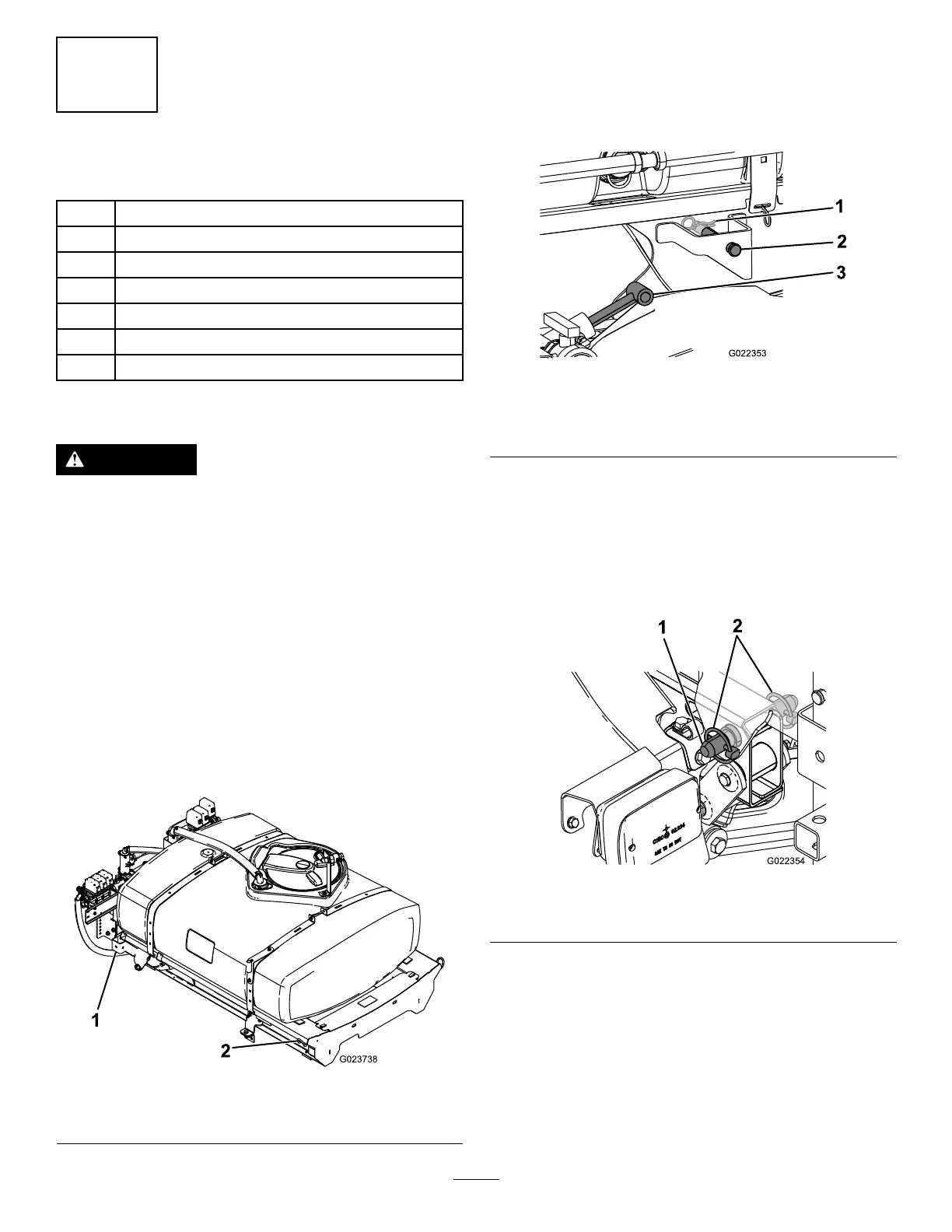
3.Extendtheliftcylinderstothebracketsonthe
tankskid,andalignthecylinderttingswiththe
holesinthetankskidbrackets(Figure9).
g022353
Figure9
1.Hairpin
3.Liftcylinders
2.Clevispin
4.Securethetankskidtotheliftcylinderswith
theclevispinsandhairpinsatbothsidesofthe
machine.
5.Lineuptheholesinthepivotlugsattherear
ofthetankskidassemblywiththeholesinthe
bedpivottubeattheendofthevehicleframe
(Figure10).
g022354
Figure10
1.Taperedclevispin2.Lynchpin
6.Installataperedclevispinand2lynchpinsto
thepivotlugtosecurethetankassemblytothe
frame(Figure10).
7.Extendtheliftcylinderstoraisethetankand
supportitsweight.
Note:Disconnectthetankassemblyfromthe
liftingequipment.
8.Removethebedsupportfromthestorage
bracketsonbackoftheROPSpanel(Figure11).
19