Fuel Gauge
The fuel gauge ( Figure 8 ) indicates the level of fuel
remaining in the fuel tank.
Height-of-Cut Switch
Use the height-of-cut switch ( Figure 8 ) to raise or
lower the cutting unit to your desired height of cut.
Height-of-Cut Gauge
The height-of-cut gauge ( Figure 12 ) indicates the
nominal cutting unit cutting height.
g431516
Figure 12
1. Height-of-cut gauge
Throttle Lever
Use the throttle lever ( Figure 8 ) to control the engine
speed. Moving the throttle lever forward toward the
F AST position increases the engine speed. Moving
the throttle lever rearward toward the S LOW position
decreases the engine speed. The throttle lever
controls the speed of the blades and, with the traction
pedal, controls the ground speed of the machine.
Hour Meter/Service Due Indicator
The hour meter ( Figure 8 ) records and displays
accumulated hours of engine operation.
Pressing the button below the display once displays
the number of hours until the next engine oil and lter
change.
Pressing the button below the display again displays
the number of hours until the next lubrication at the
grease ttings.
Pressing the button below the display a third time
returns to the working-hours screen.
Note: When there 10 hours left for an oil change, the
indicator ashes automatically with “OIL CHANGE”
when you need to change the engine oil and lter .
Note: When there 5 hours left before greasing
needed, the indicator ashes automatically with
“LUBE” when you need to lubricate the machine.
Important: During the rst 50 hours while in the
oil change mode, take care to not inadvertently
hold the button of the hour meter longer than
6-seconds. Holding the button longer than
6-seconds will set the oil service interval from 50
hours to 250 hours.
After changing the engine oil and lter or lubricating
the machine and cutting unit, perform the following:
1. Push the button until you reach the desired
screen.
2. Push and hold the button until a series of zeros
(000000) appear .
Note: Y ou cannot reset the total working hours of
the machine.
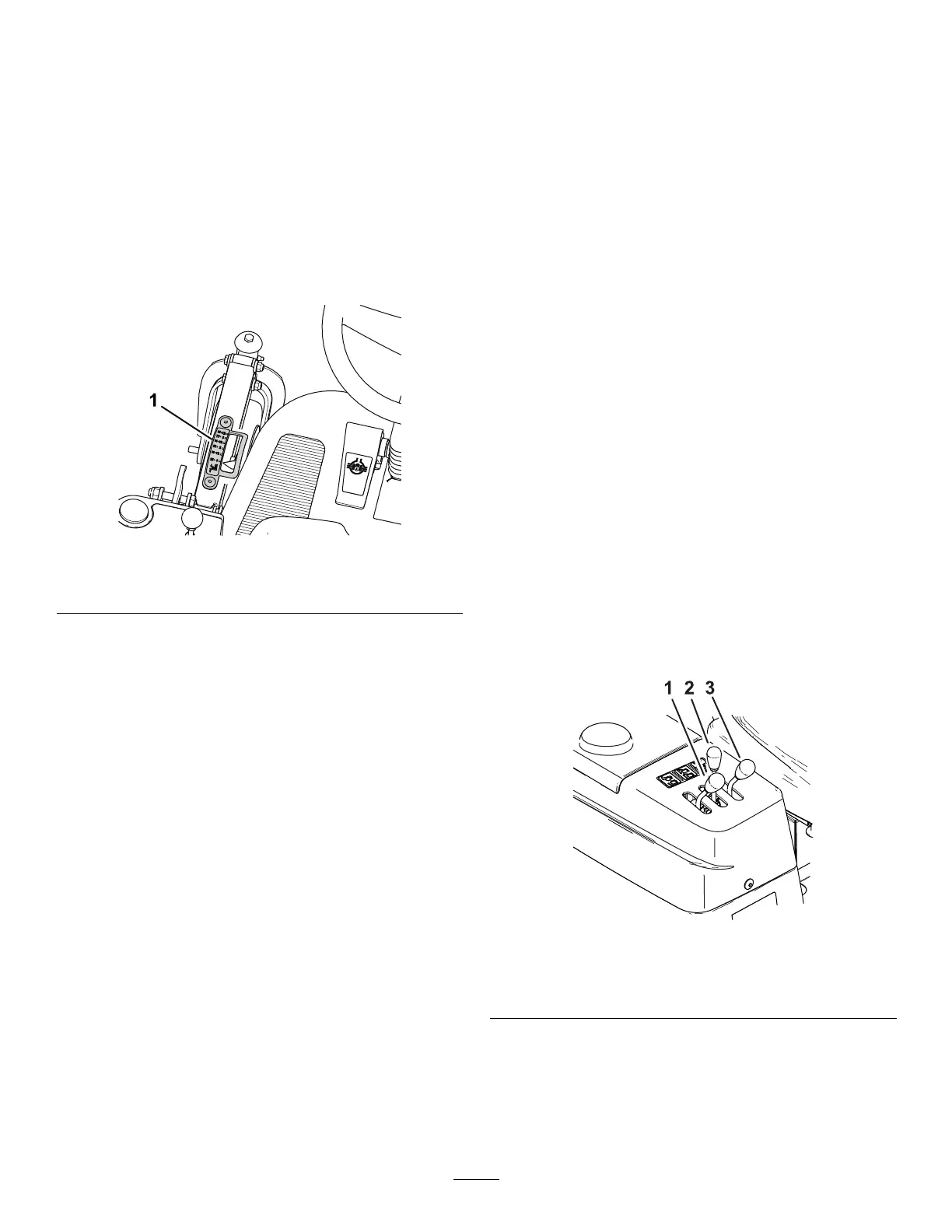
Cutting-Unit Lift Lever
Move the lever rearward to raise the cutting unit
( Figure 13 ).
Move the lever forward to lower the cutting unit and
fully forward to allow it to oat ( Figure 13 ).
Important: T o avoid damaging the cutting-unit lift
system, set the cutting-unit lift lever to the forward
( FLOAT ) position whenever you drive the machine
with the cutting unit on the ground.
Note: Lower the cutting unit and hopper whenever
you are not using the machine.
g431517
Figure 13
1. Hopper dump lever
3. Cutting-unit lift lever
2. Hopper lift lever
Hopper Lift Lever
Move the lever rearward to raise the hopper ( Figure
13 ).
Move the lever forward to lower the hopper .
20