4.8 Logic Upper Assembly 4 Replacement Procedures
Satellite A660/A665/A660D Maintenance Manual 4-27
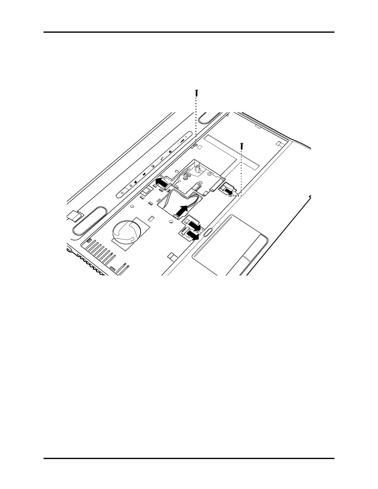
3. Disconnect the three connectors: one Control Panel FCC, one speaker cable and one
Touch pad cable as shown in Figure 4.18.
Figure 4.18 Disconnecting the cables and removing two upper logic assembly screws

 Loading...