EasyManuals Logo

Toshiba Satellite A660 Series Maintenance Manual

Toshiba Satellite A660 Series
224 pages
To Next Page IconTo Next Page
To Previous Page IconTo Previous Page
Page #187 background imageLoading...
Page #187 background image
4 Replacement Procedures 4.8 Logic Upper Assembly
Satellite A660/A665/A660D Maintenance Manual 4-28
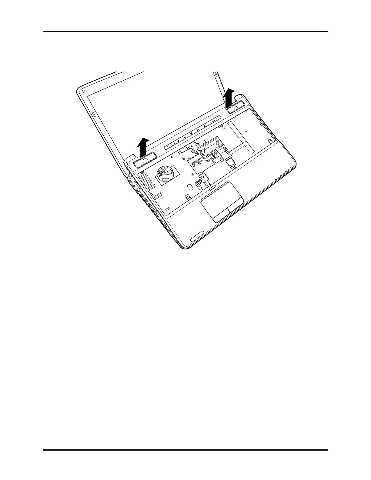
4. Pry up the logic upper assembly from the bottom edge and remove it as shown in Figure
4.19.
Figure 4.19 Removing the logic upper assembly
Installing the Logic Upper Assembly
Install the logic upper assembly according to the following procedures.
1. Seat the logic upper assembly from the back edge and adjust to the correct position. Snap
the logic upper assembly firmly into place.
2. Attach the three cables and secure the logic upper assembly with two M2.5x8 screws as
indicated in Figure 4.18.
3. Close the laptop and turn it upside down. Secure the logic upper assembly with thirteen
M2.5x8 screws as indicated in Figure 4.17.

Table of Contents

Other manuals for Toshiba Satellite A660 Series

Questions and Answers:

Question and Answer IconNeed help?

Do you have a question about the Toshiba Satellite A660 Series and is the answer not in the manual?

Toshiba Satellite A660 Series Specifications

General IconGeneral
Optical DriveDVD SuperMulti Drive
WirelessWi-Fi 802.11b/g/n
HDMIYes
Battery6-cell Lithium-ion
ProcessorIntel Core i5
RAM4GB or 8GB DDR3
StorageUp to 640GB HDD
GraphicsNVIDIA GeForce GT 330M
Operating SystemWindows 7 Home Premium or Professional
WebcamYes, with built-in microphone
AudioStereo speakers, Dolby Advanced Audio
LAN10/100 Ethernet
Card ReaderMulti-Card Reader
USB Ports3 x USB 2.0
PortsMicrophone input, Headphone output

Related product manuals