STE 80720
– 10-10 –
OPERATOR’S MANUAL
series Robot Controller
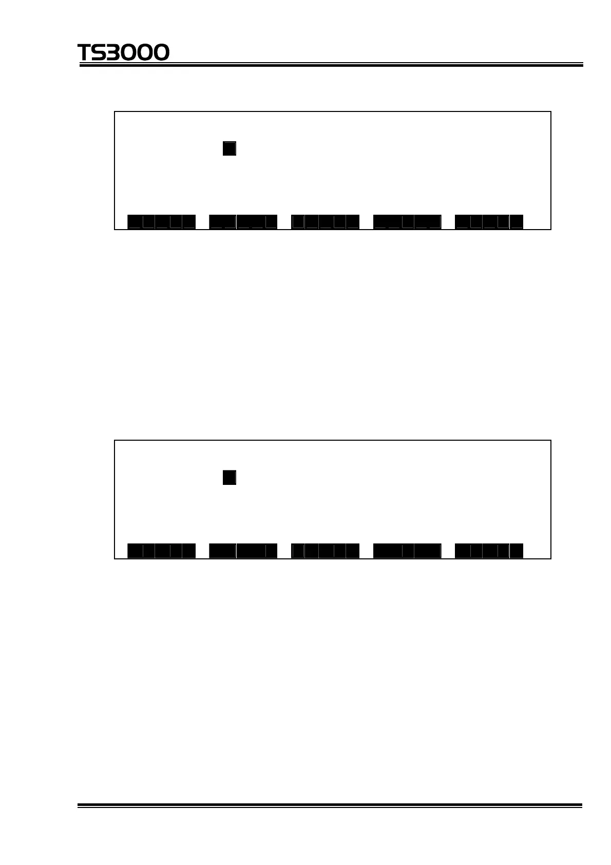
Page 5 (field bus output 2)
I / O M o n i t o r ( F i l d b u s 2 O U T ) 5 / 5
1 10 11 20
D O U T 4 0 * 0 0 000 00000 0000 0 0 0 000
D O U T 4 2 * 0 0 000 00000 0000 0 0 0 000
D O U T 4 4 * 0 0 000 00000 0000 0 0 0 000
D O U T 4 6 * 0 0 0 0 0
O N O F F D I N D O U T S Y S
• The I/O signal status is represented by "1" for open contacts and by "0" for
close contacts.
• One line contains 20 signals which are separated at every 5 signals, and the
number of the signal at the head of the signal string is displayed at the left
end of the line.
• The number of signals is 64.
• For the page where [ON] or [OFF] is displayed, data indicated by the cursor
can be set ON or OFF.
3 SYS (System)
Page 1 (HAND)
I / O M o n i t o r ( H a n d ) 1 / 4
1 5 8
D O U T 2 0 * 0 0 000 000
D I N 2 0 * 0 0 0 0 0 0 0 0
O N O F F D I N D O U T S Y S
• The I/O signal status is represented by "1" for open contacts and by "0" for
close contacts.
• The number of signals is 8 each for input and output, and the number of the
signal at the head of the signal string is displayed at the left end of the line.
• For the output signals, data indicated by the cursor (i.e. data inversely
displayed) can be set ON or OFF using the corresponding function key.

 Loading...


