TR-Electronic GmbH 2009, All Rights Reserved Printed in the Federal Republic of Germany
Page 106 of 108 TR - ECE - BA - DGB - 0070 - 17 12/13/2018
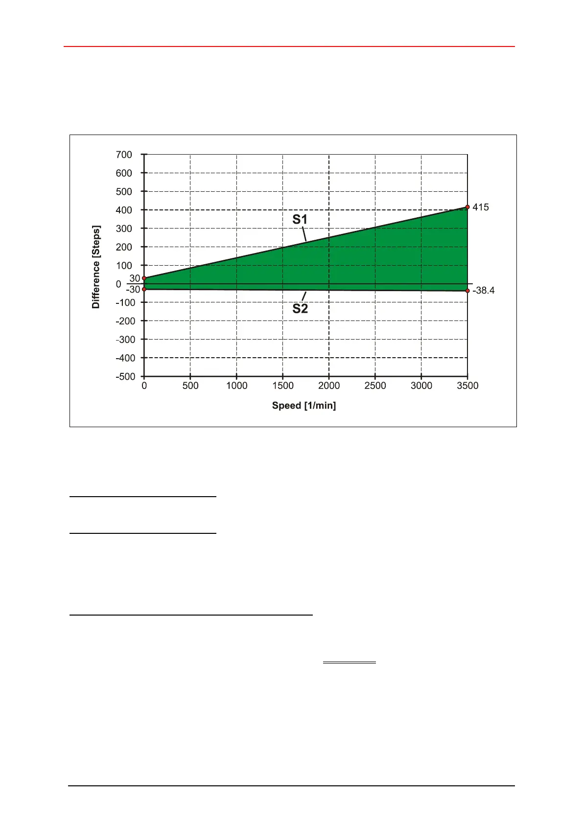
9.5 Max. possible step deviation (master system / inspection system)
Figure 19: Dynamic view of the step deviation, counting direction rising (view onto flanging)
Function of the straight line S1:
S1 = 30 steps + (0.11 steps per revol. * actual speed [1/min])
Function of the straight line S2:
S2 = -30 steps + (-0.0024 steps per revol. * actual speed [1/min])
The max. possible step deviation results from the difference between S1 and S2
Example: Max. possible step deviation at 3500 1/min
S1 = 30 steps + (0.11 steps per revol. * 3500 1/min) = 415 steps
S2 = -30 steps + (-0.0024 steps per revol. * 3500 1/min) = -38.4 steps
Max. possible step deviation = 415 steps – (-38.4 steps) = 453.4 steps