TR-Electronic GmbH 2009, All Rights Reserved Printed in the Federal Republic of Germany
Page 78 of 108 TR - ECE - BA - DGB - 0070 - 17 12/13/2018
4 Assembly
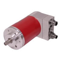
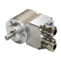
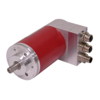
4.1 Solid shaft version CDV-75
The measuring system is connected to the drive shaft by an elastic coupling. Axial and
radial deviations between the measuring system and the drive shaft are absorbed by
the coupling. This prevents excessive bearing loads.
The centering collar with appropriate fit ensures centering in relation to the shaft.
Fixing to the machine is made by means of three screws in the flange.
All fastening screws must be secured against unintentional loosening.
4.1.1 Requirements
● Danger of death, serious physical injury and/or damage to property
due to deactivation of safety functions, caused by an unstable shaft
drive!
The system manufacturer must implement suitable design measures, so
that the drive of the measuring system is ensured at all times through
the shaft and mounting of the measuring system (fault exclusion). The
specifications of DIN EN 61800-5-2:2008 "Adjustable speed electrical
power drive systems, Safety requirements - Functional, Table D.16 –
Motion and position sensors" must be observed.
In general, the requirements and acceptance
conditions for the complete
system must be taken into account for mounting.
As the installation situation is application-dependent, the following
notes are not exhaustive.
A suitable coupling with positive connection must be used for the
application.
The coupling manufacturer's information and installation requirements
must be observed.
In particular, you must ensure that
– the coupling is suitable for the specified speed and the potential axial
offset,
– installation is on a grease-free shaft,
– the coupling and the measuring system are not axially loaded,
– the clamping screws are tightened with the torque defined by the
coupling manufacturer,
– the coupling screws are secured against unintentional loosening.
Axial slipping of the measuring system on the drive shaft must be
prevented by the coupling fixing, see Figure 2, 1 .
Radial slipping of the measuring system on the drive shaft must be
prevented by means of form closure, using a parallel key / groove
combination (Figure 2, 2 ); a coupling with groove must be used for this
purpose.
In case of applications with low ambient temperatures, increased values
for the start-up torque result. This fact is to be considered when the
assembling and wave drive is performed.