Installation / Preparation for Commissioning
TR-Electronic GmbH 2009, All Rights Reserved Printed in the Federal Republic of Germany
Page 92 of 108 TR - ECE - BA - DGB - 0070 - 17 12/13/2018
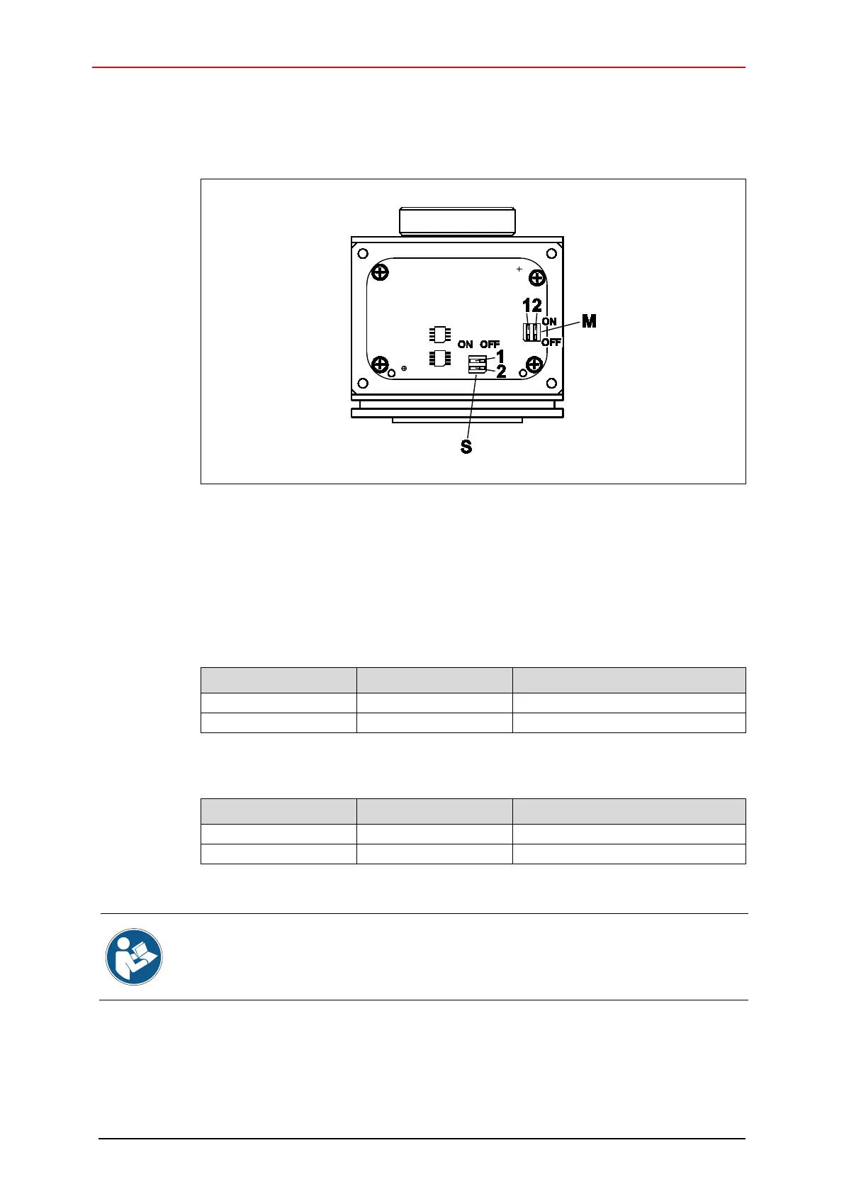
5.5 Counting direction
Figure 10: Setting of the counting direction
M: Master-System
S: Safety-System
1: DIP-switch, Counting direction
2: DIP-switch, internal diagnosis
Permissible switch positions Master-System:
DIP-switch 1 DIP-switch 2 Counting direction
cw increasing, view onto flange
cw decreasing, view onto flange
Permissible switch positions Safety-System:
DIP-switch 1 DIP-switch 2 Counting direction
cw increasing, view onto flange
cw decreasing, view onto flange
Non-permitted switch positions lead to the passivation of the related SSI-Channel and
are signaled by the corresponding Error LED. In the other channel the SSI-
set.
Reset: Adjust permissible switch position, Power OFF/ON