Installation / Preparation for commissioning
TR-Electronic GmbH 2004, All Rights Reserved Printed in the Federal Republic of Germany
Page 68 of 112 TR - ECE - BA - DGB - 0036 - 16 11/05/2018
4.2 Type with cable glands
4.2.1 Connection
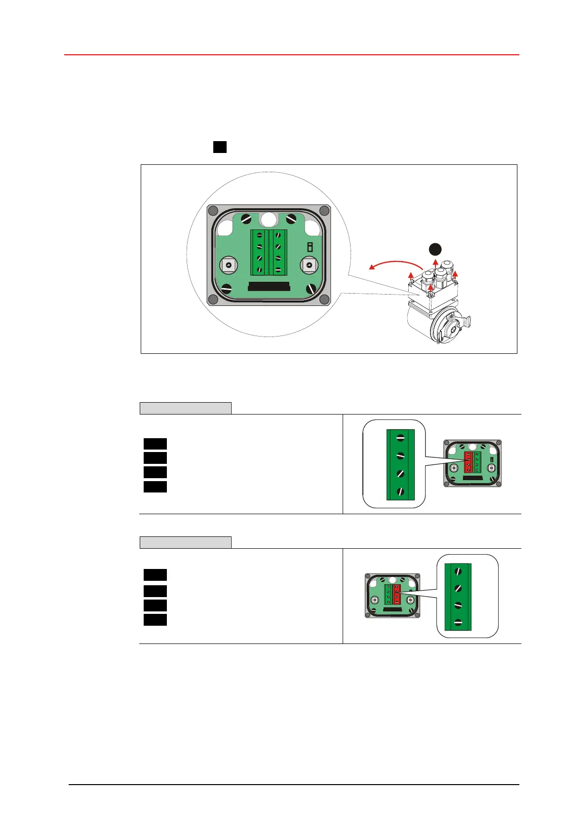
The connection hood must first be removed from the measuring system to undertake
connection.
The four screws (A) are unscrewed and the hood removed.
1
0
1
2
3
4
5
6
7
8
9
0
1
2
3
4
5
6
7
8
9
1
A
Figure 1: Removing of the connection hood
Pin 1 PROFIBUS Data A
Pin 2 PROFIBUS Data B
Pin 3 Supply voltage, 11-27 VDC
Pin 4 0 V, GND
Pin 1 PROFIBUS Data A
Pin 2 PROFIBUS Data B
Pin 3 Supply voltage, 11-27 VDC
Pin 4 0 V, GND
The terminals for the supply voltage (pin 3 / pin 4) are connected together internally
and can be used as feeding, as well as supply voltage for the subsequent slave.
0
1
2
3
4
5
6
7
8
9
0
1
2
3
4
5
6
7
8
9
1
IN
0
1
2
3
4
5
6
7
8
9
0
1
2
3
4
5
6
7
8
9
1
OUT